
Steve
-
Posts
10506 -
Joined
-
Last visited
-
Days Won
2
Content Type
Profiles
Forums
Store
Blogs
Events
Downloads
Supra Articles
Gallery
Everything posted by Steve
-
IIRC the FPC wire (Purple/White) from the main ECU just gives a 0v feed when turned on, so this could be used to fire a separate relay which control the power to the pump which.
-
http://www.garagewhifbitz.co.uk/index.php/toyota-1289.html
-
Not sure..... IIRC 2 of the wires are bigger than the other 2. Will have to get Homer to get a picture.
-
If that's the right one it's just the plug we need, the current one is split so the pins are exposed.
-
Under the passenger side headlight there is 2 relays mounted to the chassis. The one nearer the front I believe is the fan relay, the plug on this is split so needs changing.
-
Was just looking, looks like the Radiator Fan Relay. If not I will have another go at that old loom.
-
Did you track down that relay 4pin plug?
-
It looks right on the picture......
-
Glad you found it, all I could see was the reference to it of E4
-
89570-14240 if that is the number that is currently laying in the boot then that's fine Been a long day, I can't remember Worse case the plug for the UK ECU would be fine:)
-
IIRC it runs 9v under light load then goes full 12v+ under high load.
-
Yes, if the car is involved in an accident there is the chance if it is wired like that the pump wouldn't shut down and just continue pumping fuel.
-
Just to add to this after spending a couple of hours today going through the wiring. All the wires check out ok back to the ECU and EFI 2 relay in the fuse box. The main ECU is sending the correct signals to the Fuel pump ECU via the DI and FPC terminals, there is power at the Fuel Pump ECU but the Fuel Pump ECU is not giving the output to the pump. Also to add the Diag port override is not actually connected at all to the pump. It goes to the wing connector near the Main ECU but does not come out of there and along the wiring along the passenger sill. That pin and wire is not there at all so explains why the override isnt working. So it just seems that it is the Fuel Pump ECU that is at fault
-
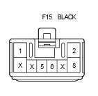
There is 5 wires on the J Spec, but on the UK there is 8 pins, but from searching around only 5 are used. Thanks Lee
-
Lee, the UK Fuel ECU is part number 89570-14230 IIRC, this has a different connector on the bottom than the JSpec (89570-14240), have you got a picture showing the connections to the UK ECU connector? I want to make sure nothing is crossed over between the 2 variants. Darryl has the UK ECU but unfortunately no connector with the original wires to check.
-
That will be the next thing to check really, each joint from front to back.
-
We have a new one which currently is laying in the boot until we get under the car to fit it properly
-
Thread in Tech for fuel pump issue - http://mkivsupra.net/vbb/showthread.php?298998-Fuel-Pump-issue&p=3762703#post3762703
-
I will try and explain this the best I can. This is on Homers RSP car that we are putting back together, so far we have been unable to get the fuel pump working with the Fuel ECU. We have tried with the link in the diag port in the engine bay (thus bypassing the Fuel Pump ECU), we should be seeing a continuous 12v at the pump, but with the connector plugged in to the top of the hanger the pump does not work. I then tried unplugging this and using a multimeter see what voltage we are getting, it starts at 12v, but continuously drops, after 10-15 seconds it is down to around 7.30v and slowly still dropping. If you remove the multimeter from the connection, give it 30 seconds or so and re-connect the meter, it is back up to around 12v, but then starts to drop again. With it connected into the hanger again you don't get a voltage at all. I have been looking over the wiring diagrams and it looks like the FP terminal in the Diag port is connected straight to the +'ve side of the pump. Between the -'ve of the battery and the B+ in the diag port is a steady 12v, so linking this to the FP terminal should give us a steady 12v at the pump. Other than now checking those wires from the front to the back I am not sure what is going on with this. Any ideas? Wiring diagram can be seen on the attached PDF, page 8 for the fuel pump wiring. wiring diagrams.pdf
-
I could relieve you of those spare wheels you have.......
-
Are you also 100% sure you have the boost controller plumbed in correctly?
-
I would be checking the wastegate pipe that goes from the collector, there was a stage where this opening was to small so the boost couldn't be controlled.
-
What exhaust manifold is it?
-
Baz, You need to be a Paid Member to post in the For Sale/Wanted section or use the PM system.
-
