dandan
-
Posts
4928 -
Joined
Content Type
Profiles
Forums
Store
Blogs
Events
Downloads
Supra Articles
Gallery
Everything posted by dandan
-
Pics?
-
Bear with me on the images - I'm having a rearrangement in Photobucket.
-
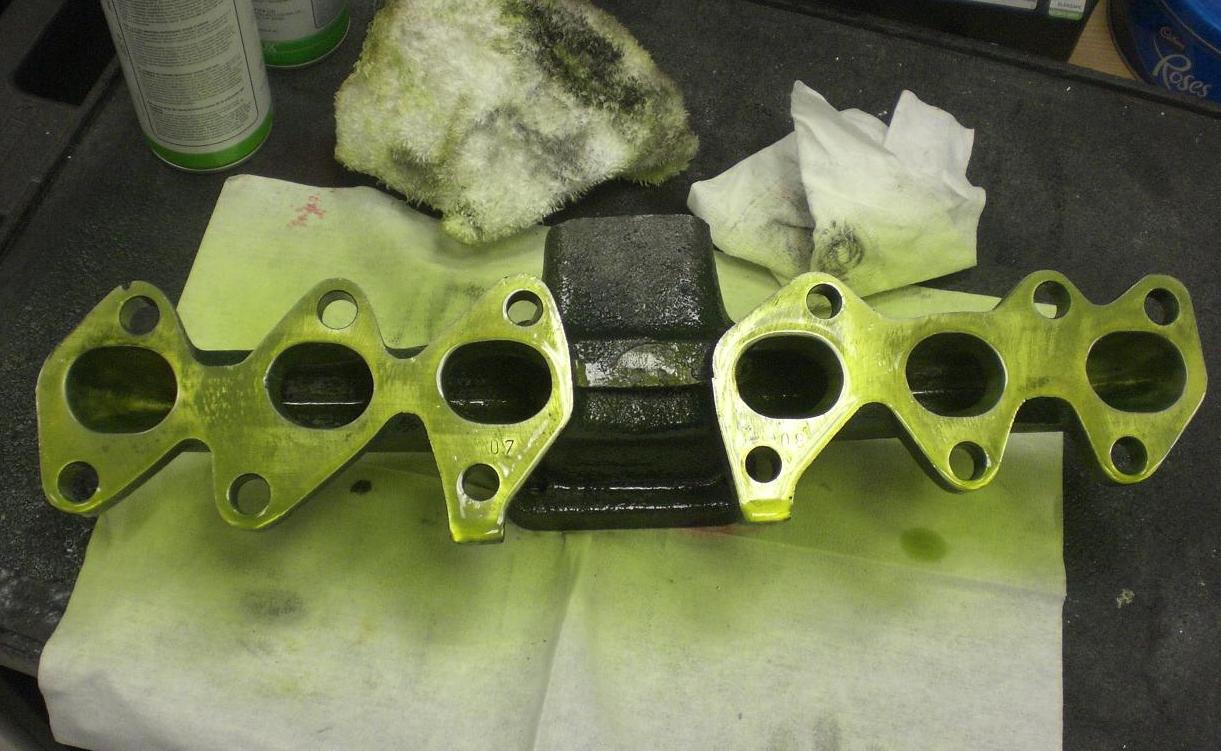
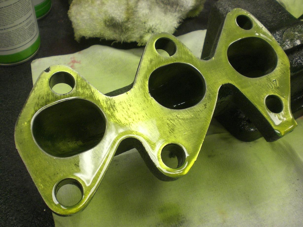
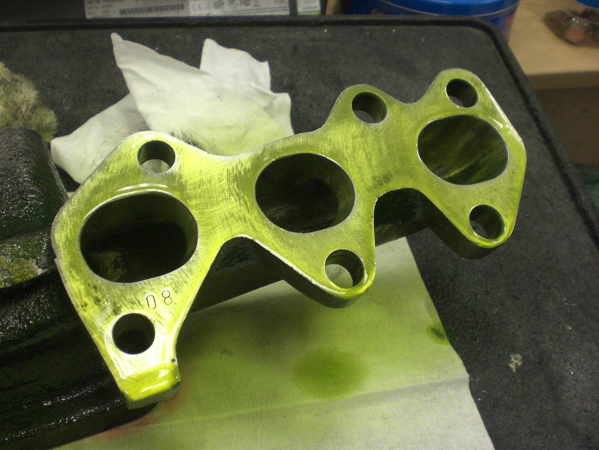
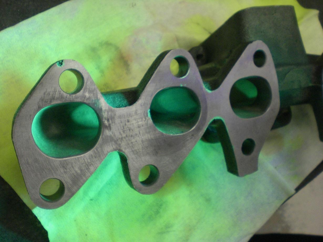
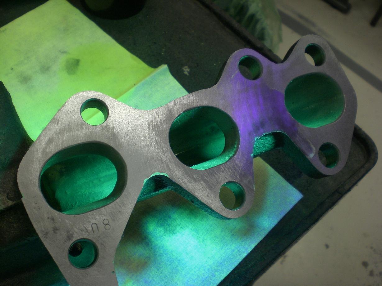
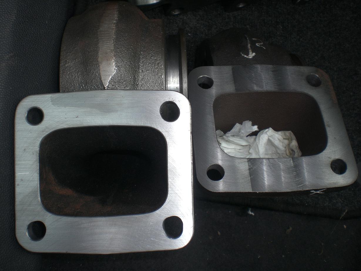
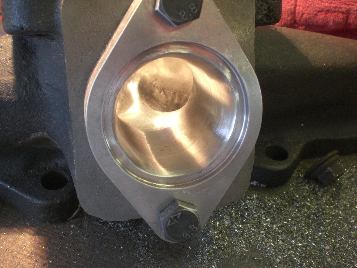
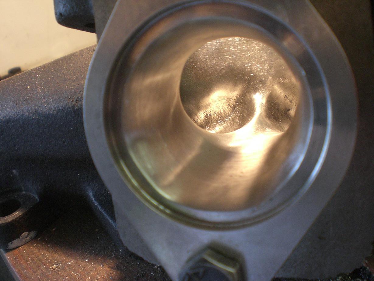
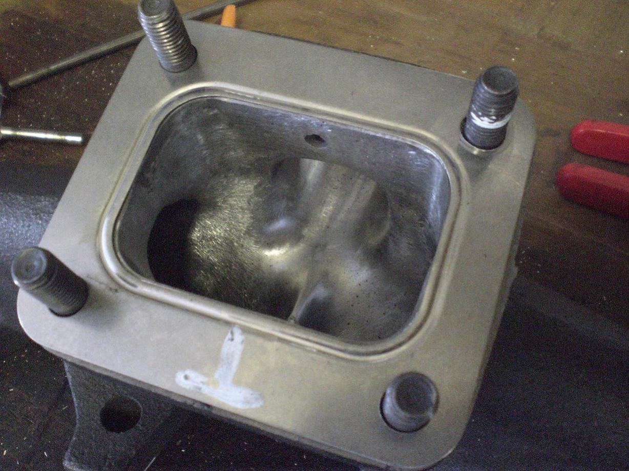
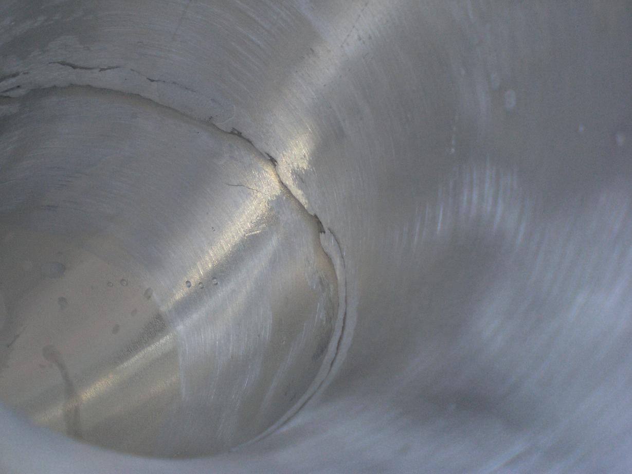
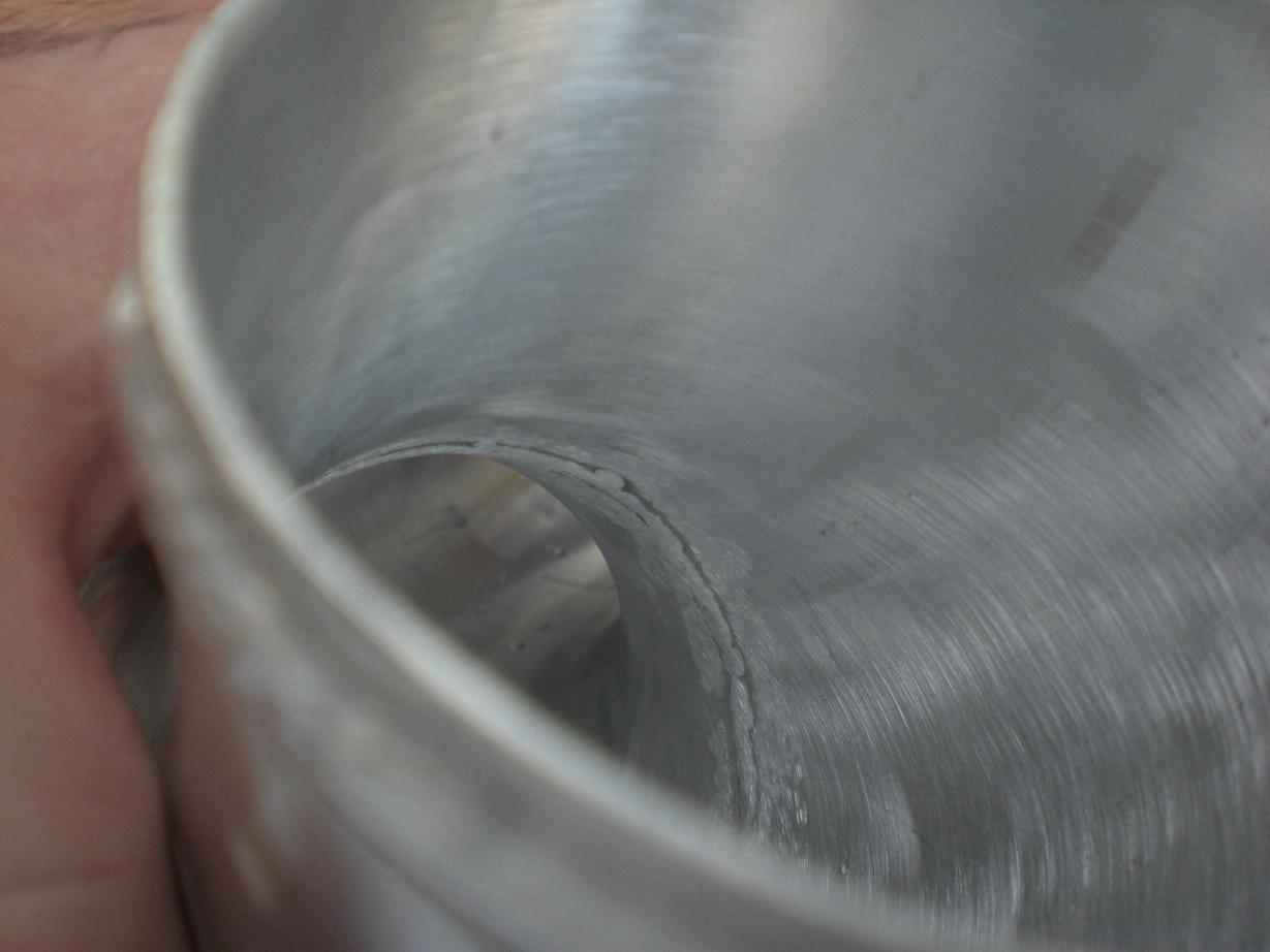
I had the manifold faces and turbine housings crack tested before going any further with any porting and ceramic coating. The general process was to clean (with a specific cleaner), spray on the penetrant dye, leave for a number of minutes, clean off all dye from surfaces to be looked at, spray on developer, leave for a few more minutes.......look for cracks with a special light. Any cracks (or porous areas) would hold dye even after being wiped clean. Then, when the developing powder goes on the surface it pulls the dye out from the cracks and shows up under the light. Penetrant in place Developing powder which would show up cracks if they were there You can get an idea of how the dye would show up a crack by looking at the last two photos and looking at the gasket face. There are a few little areas where some porosity breaks through to the surface and some edges which haven't been deburred yet. These hold the dye like a crack would and show up as bright green under the light. Fortunately there aren't any cracks so I can press on without worrying about wasting time........
-
I've been having so many things coming and going in the post and had some ongoing crap with a missing parcel I've almost developed an aversion to the post office so couldn't bring myself to send it Will do mate, stay tuned
-
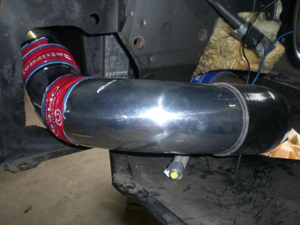
When you say "difference" - I take it you mean the cast manifold helped spool the turbo up faster? Were you rinning 3" or 4" downpipe? At least you have it there in case you need it The intercooler piping took a lot of effort and messing around. I'm very happy with how it's turned out and the routing. Now I need to get some bosses welded on for temperature measurement points, a water injection nozzle and the flange for the blow off valve. Ryan will be doing the mapping.
-

group buy Uprated ally Radiator Expansion Tank
dandan replied to johnd-mkiv's topic in Parts for Sale
I am going to need two tanks John - catch tank and water/meth storage tank. The catch tank will need to sit up near the brake servo area between the firewall and strut tower (which means its underside will need a bit of a funky sloping shape). That one will need four -10 fittings welded to it, one -6 fitting weded to it and one 1/8"NPT fitting welded to it. (I have all these weldons ) It will also need at least one baffle inside to prevent incoming flow from two of the -10 fittings being able to flow directly out of the rest. I'll try to get something mocked up in cardboard and get a few photos taken as a start. The water tank will have to sit up in the charcoal cannister area but I need to mount my Aeromotive FPR regulator first to see what room is left. -
Would you get away with 865's and upping the fuel pressure? http://www.mkivsupra.net/vbb/showthread.php?t=193721 Assuming you're running 3bar rail pressure you would only need to up that to 4bar to get 1000cc from these...just a thought
-
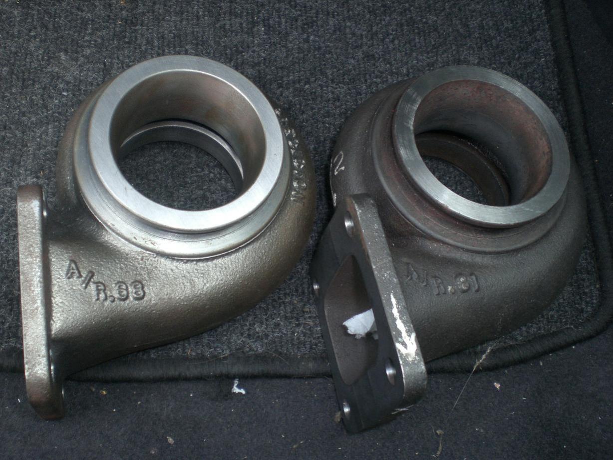
My initial thoughts were to go with the 0.68 Jamie. I figured I'm not likely to find it lacking in the top end whereas if I made a poor choice with the 0.81 then I'd definitely be disappointed with the spool and low end torque Your comments on the spool are encouraging to hear John although I can see why you moved on if you were getting boost spikes up at 1.8bar! What turbo were you running on that manifold, something smaller than a 67mm? It isn't a five minute job porting the manifold but it could be made a lot easier by simply machining it out to an acceptable size and then tidying up the transition area by hand. I guess I'm a glutton for punishment so I did it all by hand!
-
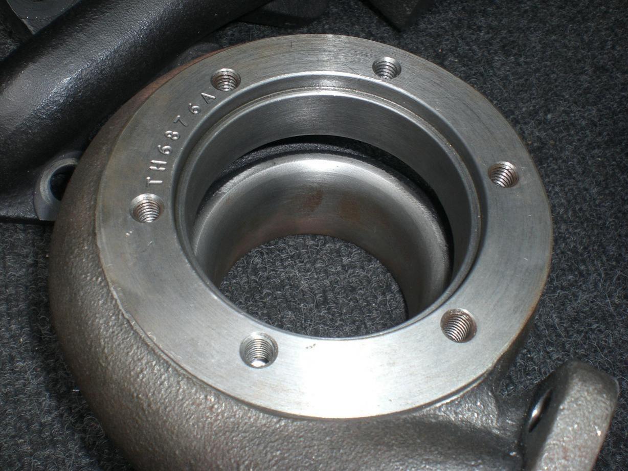
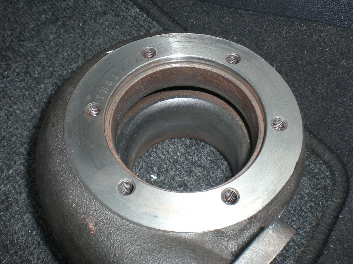
I had all the manifold, turbine inlet and V band faces checked for flatness and the ones that weren't perfect were machined flat. I'm not 100% sure if I'll be going with a 0.68 or a 0.81 turbine housing. I'm thinking the 0.68 should really have plenty low down pull with this manifold so should be excellent as a daily driver type car. On the other hand, the fast spooling characteristics of the cast manifold may give enough low rpm benefit to get a fast (ish) spooling setup with the 0.81 combined with its top end power advantage over the 0.68.........hmmmm.......choices. The 0.81 does need a little cleanup whereas the 0.68 is brand new.
-
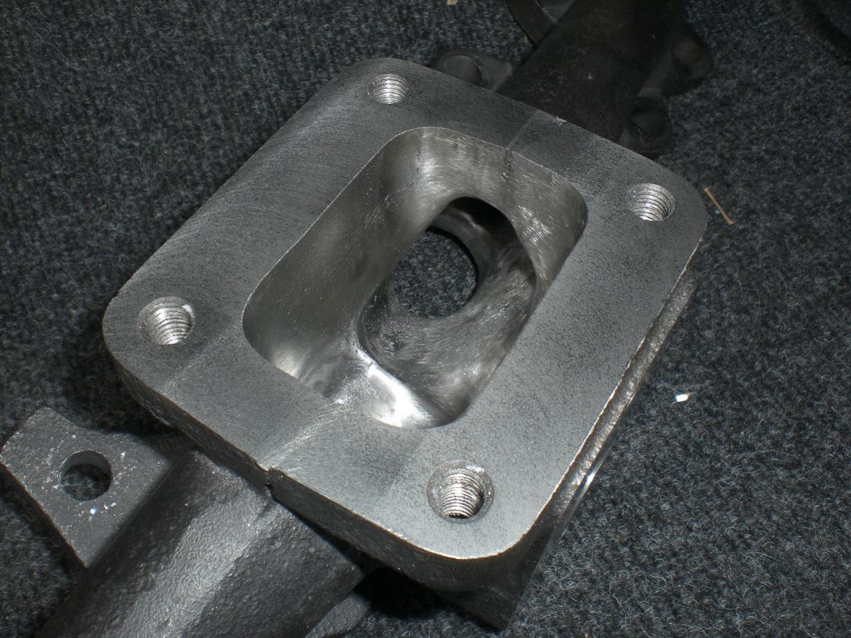
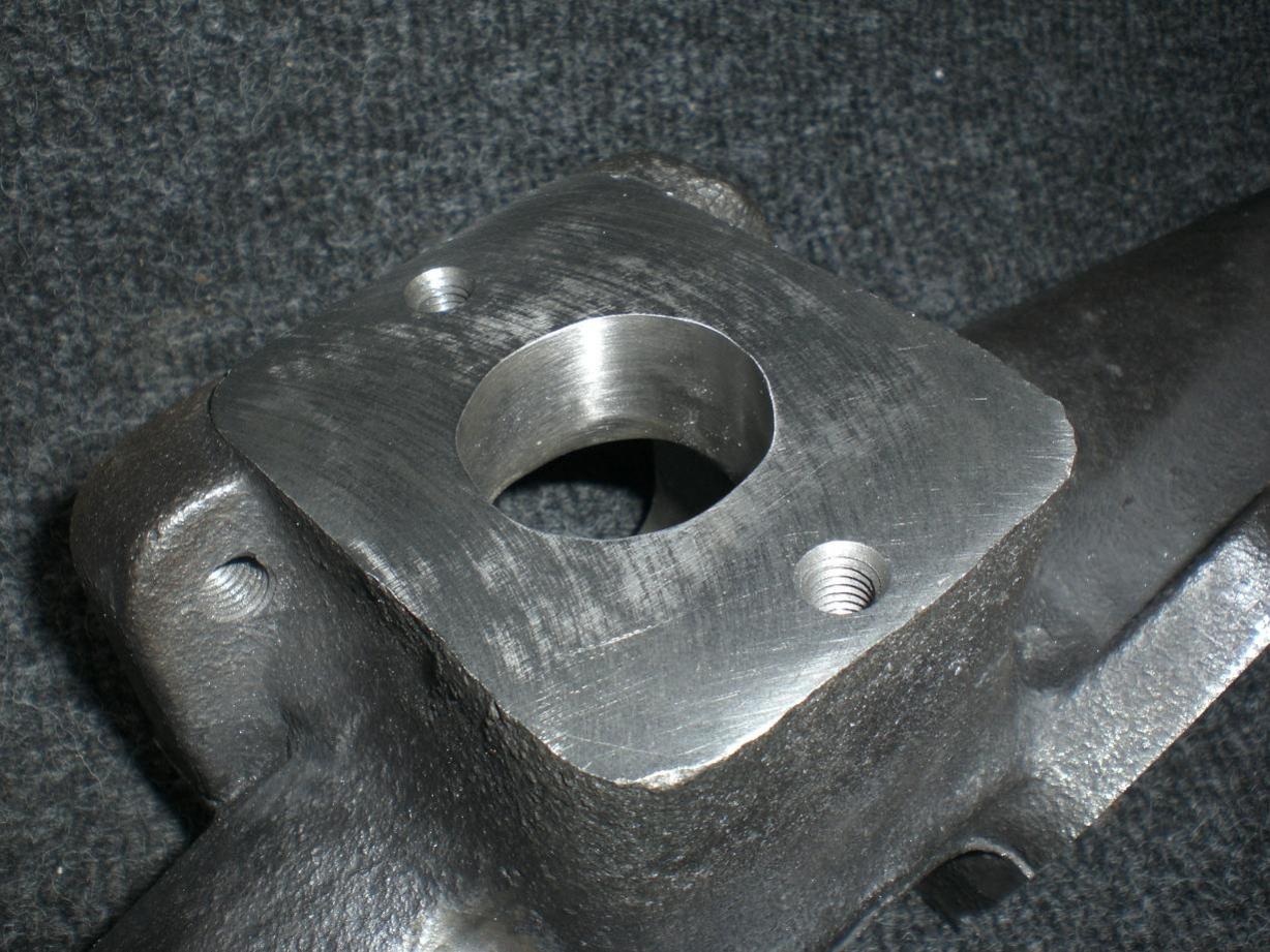
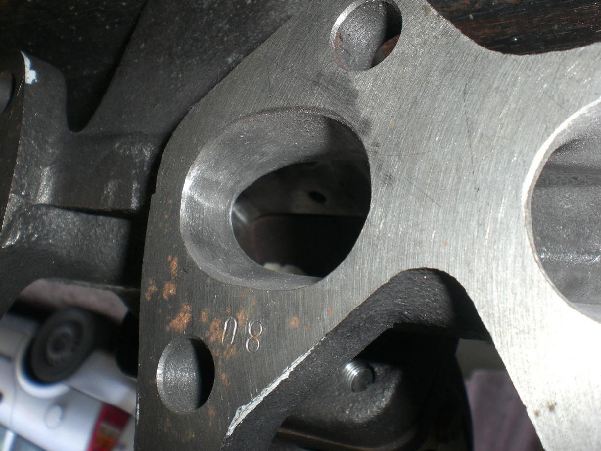
I've added this one to show the wastegate port area on this manifold. As you can see, there is plenty material cast around the wastegate port region. There's lots of room for opening up to gain flow area without ending up with a wafer thin region trying to hold a gasket on this face. I've heard quite a few (second hand) stories about the Turbonetics manifolds leaking after a while if heavily ported. On the other hand I've heard stories of boost spikes if the Turbonetics manifold's wastegate outlet is left untouched. So I think if you have one of those manifolds it may be a bit of a "rock - hard place" scenario regarding porting if you're running biggish power with not much boost. I don't think it will be be a probem with this manifold setup. The wastegate outlet is pretty big and will flow well
-
I think the manifold came with a 32mm hole for the wastegate. Mine has now been hogged out to something more like 40mm at the narrowest point. This is in a short region roughly at the manifold face which you can just about make out if you try to look for a line where the flange is meeting the manifold.

-
Thanks Gaz, will do Cheers Mig. I'm feeling a bit under pressure now with eyes watching! I did ask you if you had any other useful bits tucked away in your garage No worries though, I had a spare anyway so no big deal.
-
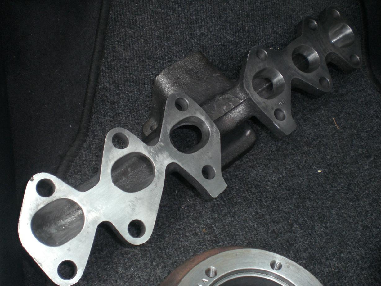
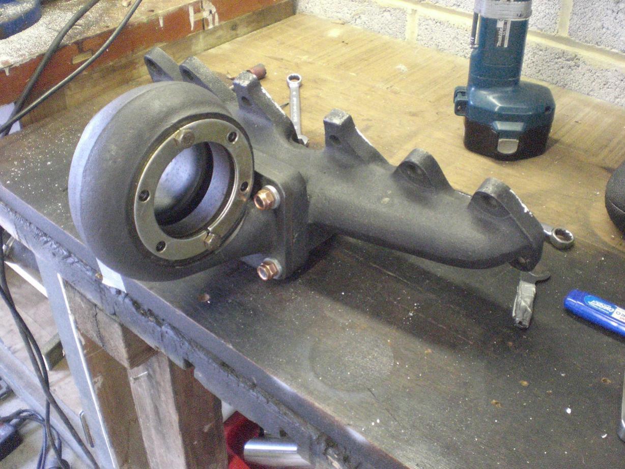
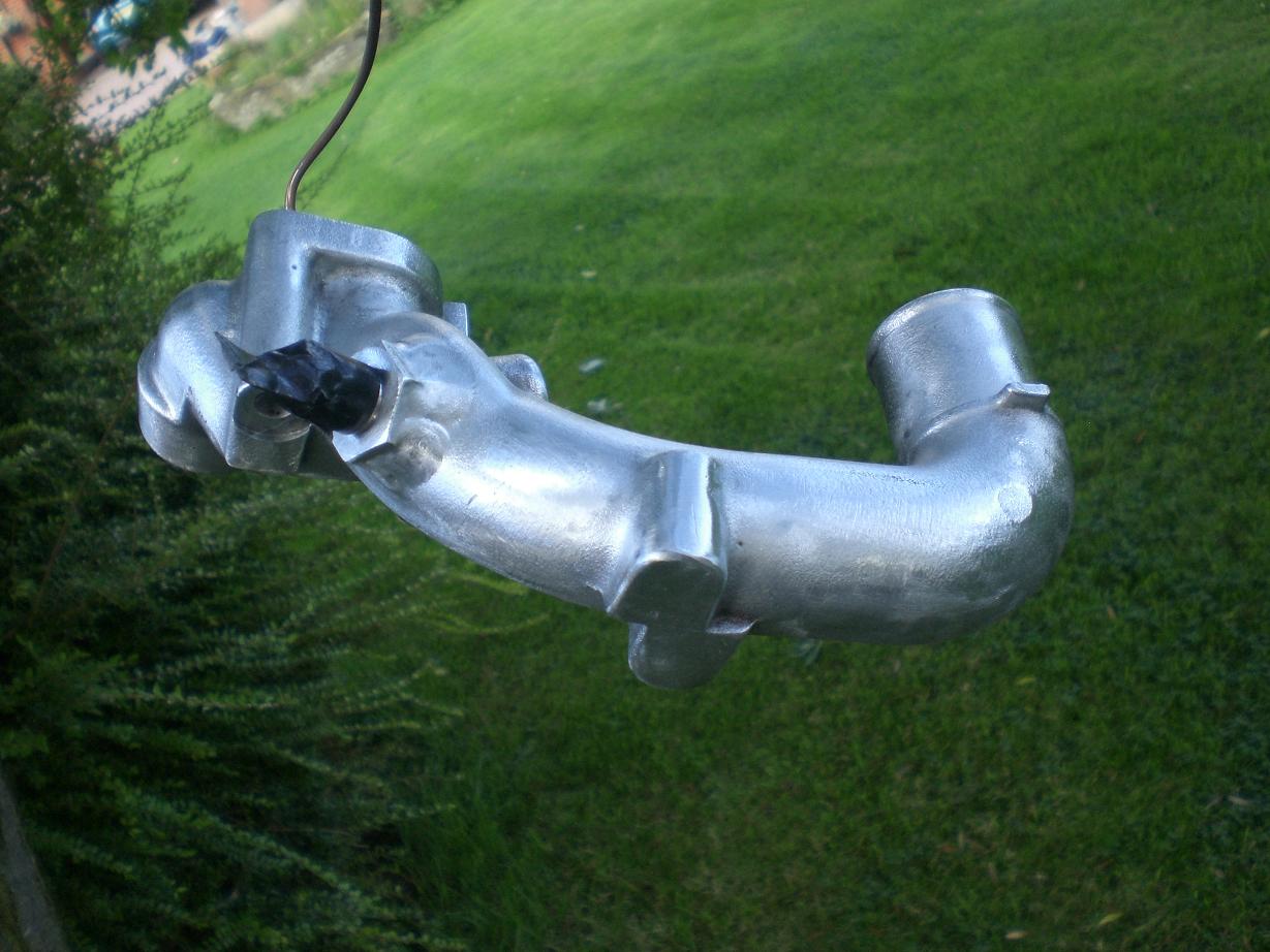
Here's a few photos of the cast exhaust manifold when I was doing the initial port matching.... There's something very neat looking and functional about the cast setup in my opinion.
-
I'm not sure off the top of my head Christian, it could well be. I'm going to try to get some of the R10 this week....
-
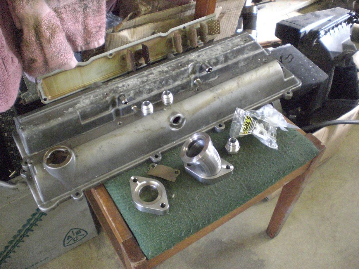
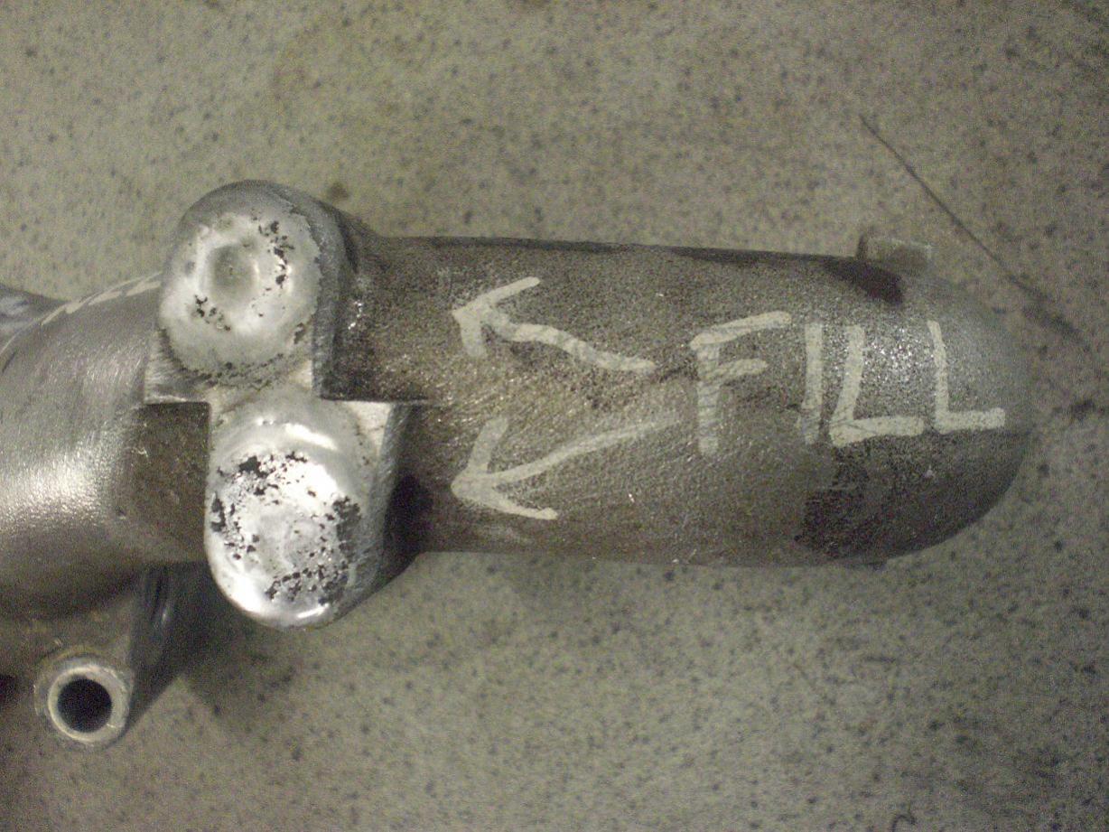
I also got the baffles removed from the cam covers so they are ready for welding now as well. A #10 aluminium weld on boss is going on each cover.
-
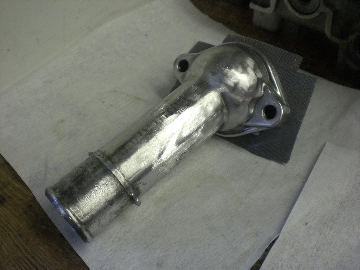
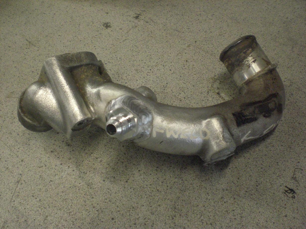
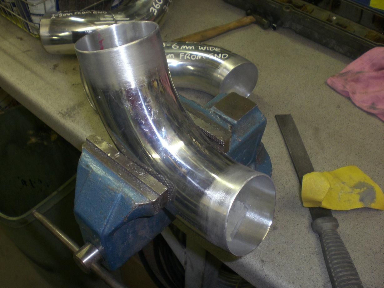
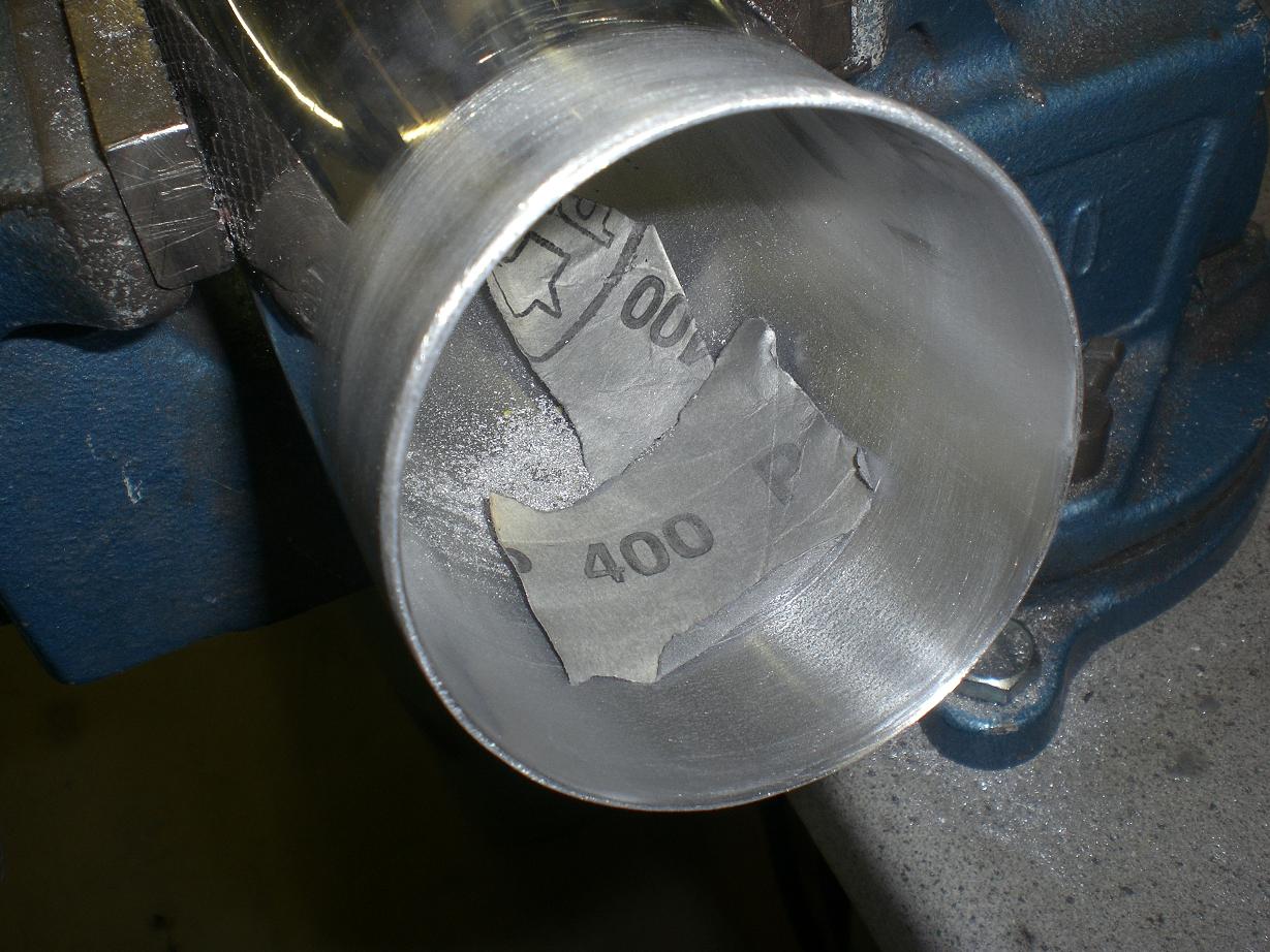
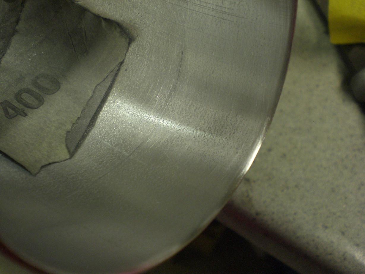
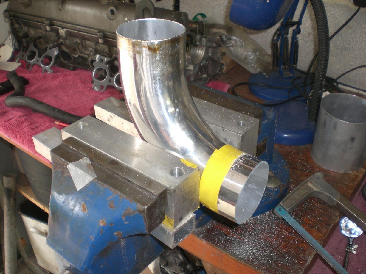
This afternoon was mostly spent prepping the aluminium parts.....intercooler pipes, water neck, stat housing etc. Grinding down the welds inside the intercooler pipes was a little tricky on some of the bends but they were nice and smooth after some perseverence with the die grinder. I had to use a mirror and grinding stone on an extension a bit like the dentist working on the back of one of your molars!
-
Thanks for the offer Kev, much appreciated. I may well take you up on that but right now it's itty bitty jobs that need sorting like prepping parts ready to fit so nothing too major happening yet. Tell me about it, I've been waiting to get started on this upgrade since about January. Thanks Ricky
-
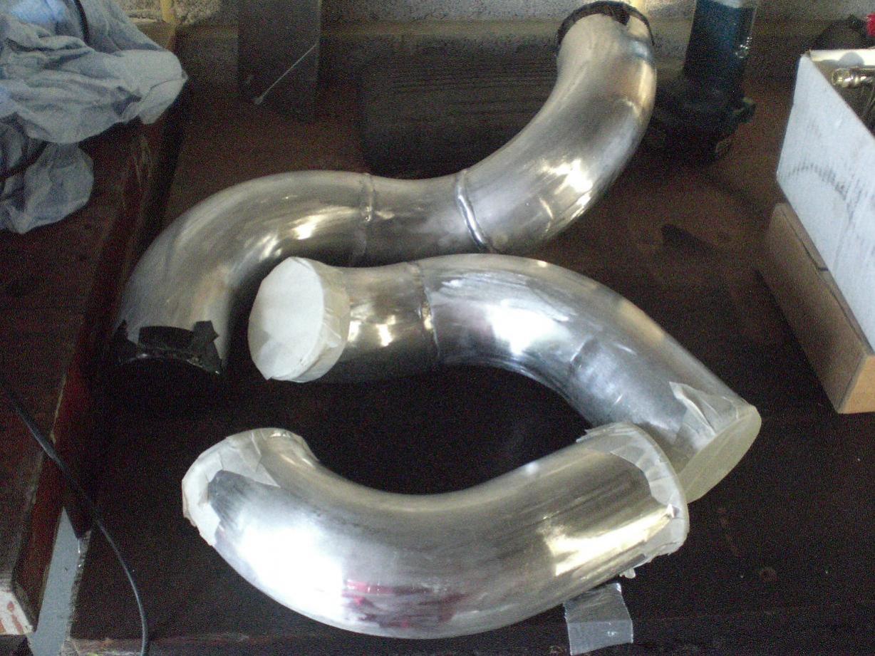
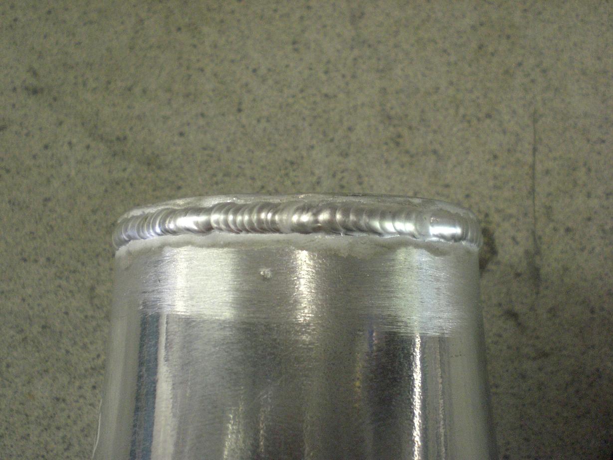
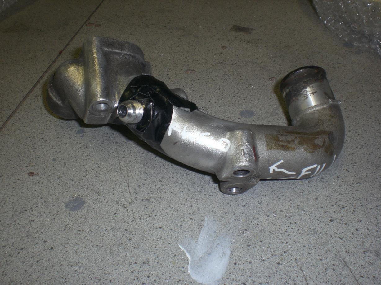
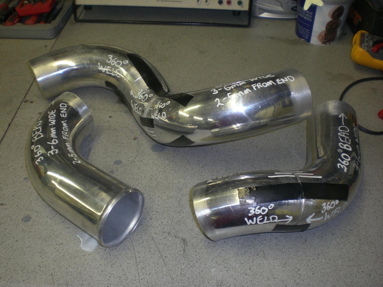
Sound advice Paul - thanks. Here's how the piping looks after welding.....not a bad job at all, I'm very happy with the quality this guy can produce especially as I told him not too be tooo fussy with the OD of the pipes as they'll be painted/coated anyway. A good rub down now and they'll be looking perfect. I used a spare water elbow (thanks Charlie - it's been in the garage for about 3 yrs along with the spare engine!) as I didn't want to risk making a mess of mine...as it happened it was no big deal.
-
OK fellas - how about SAE J30R6?
-
Intercooler pipes and water neck/elbow being prepped for welding.... [
-
Thanks fellas, I can't wait to get it back on the road. It'd be nice to take a week or so off work to get it all done; as things stand I'm getting about two evenings a week on it and roughly a day at the weekends so it's dragging a little.
-
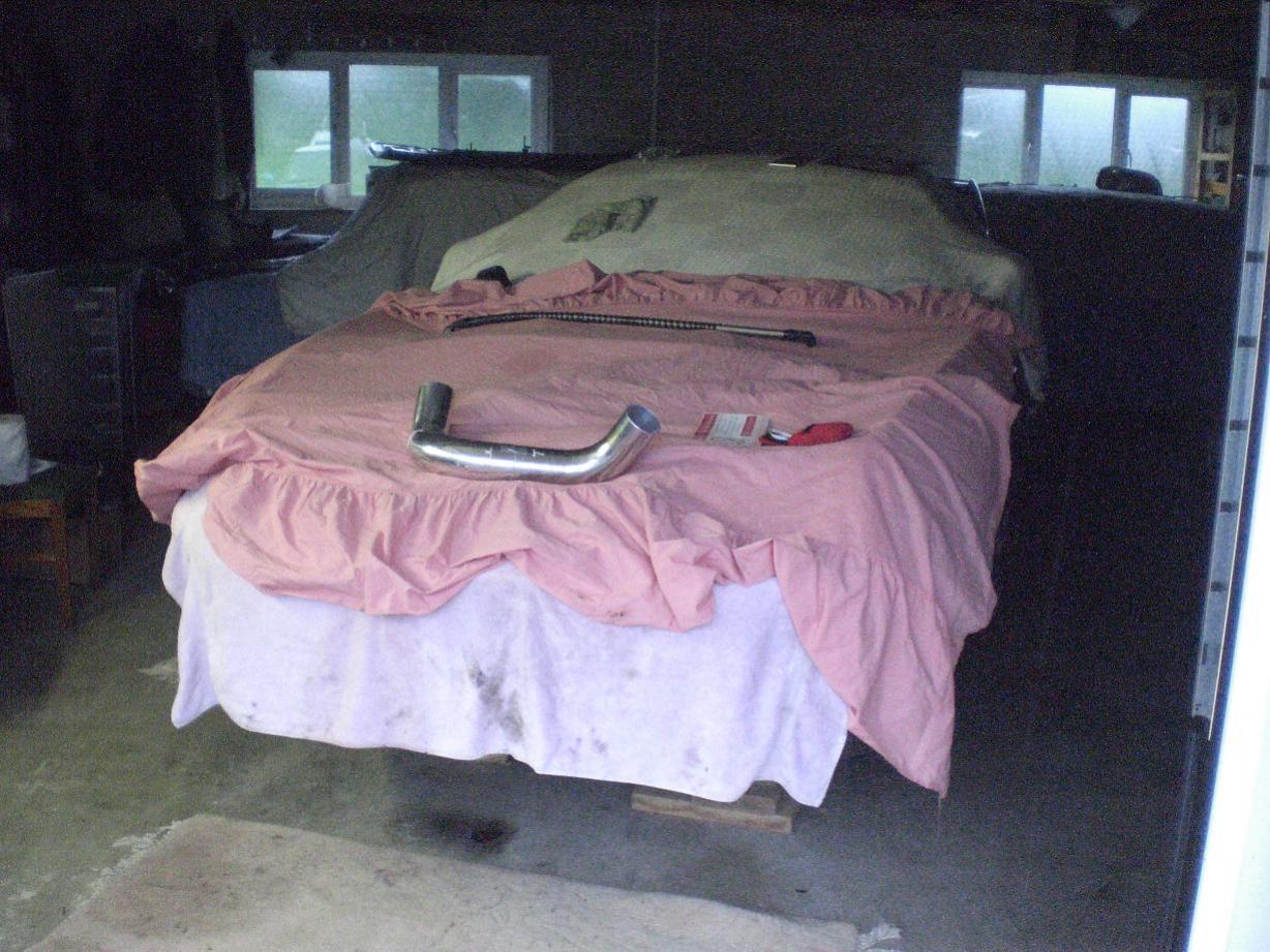
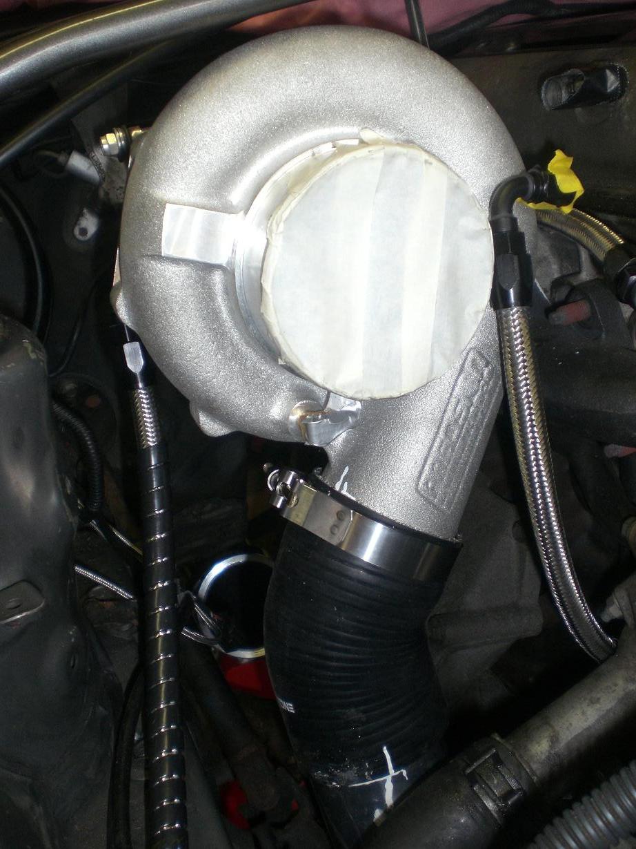
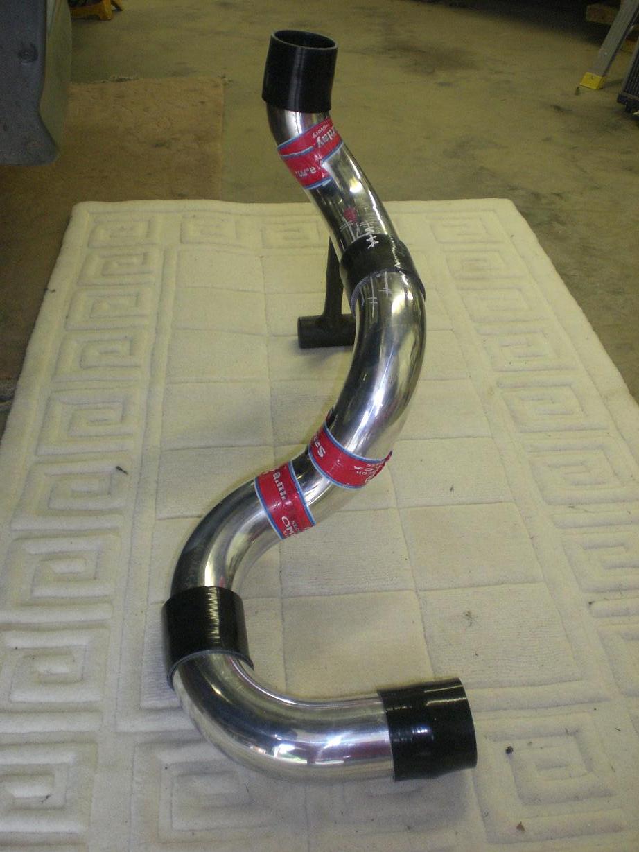
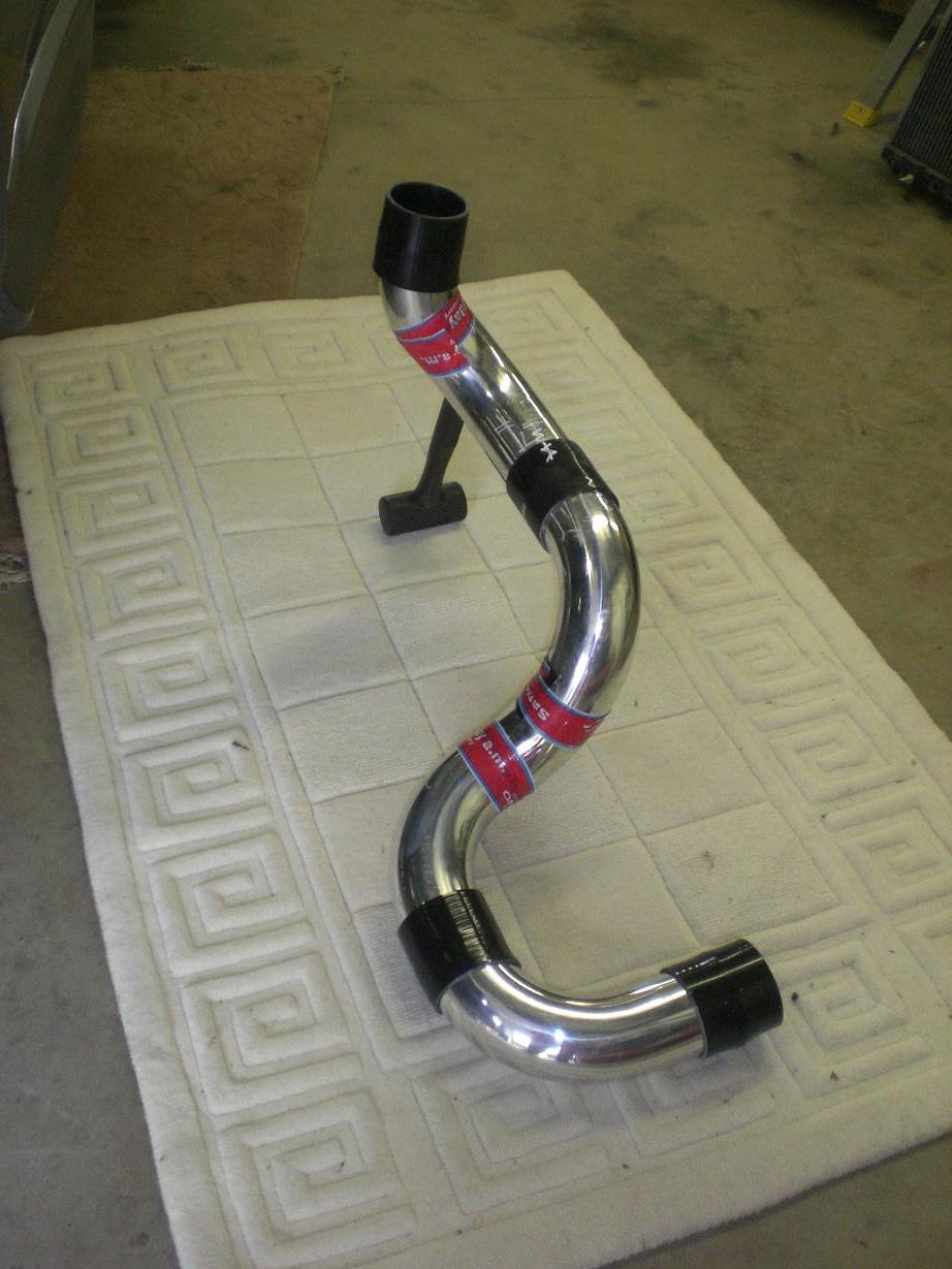
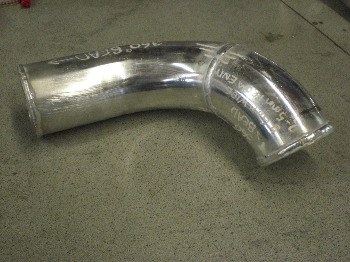
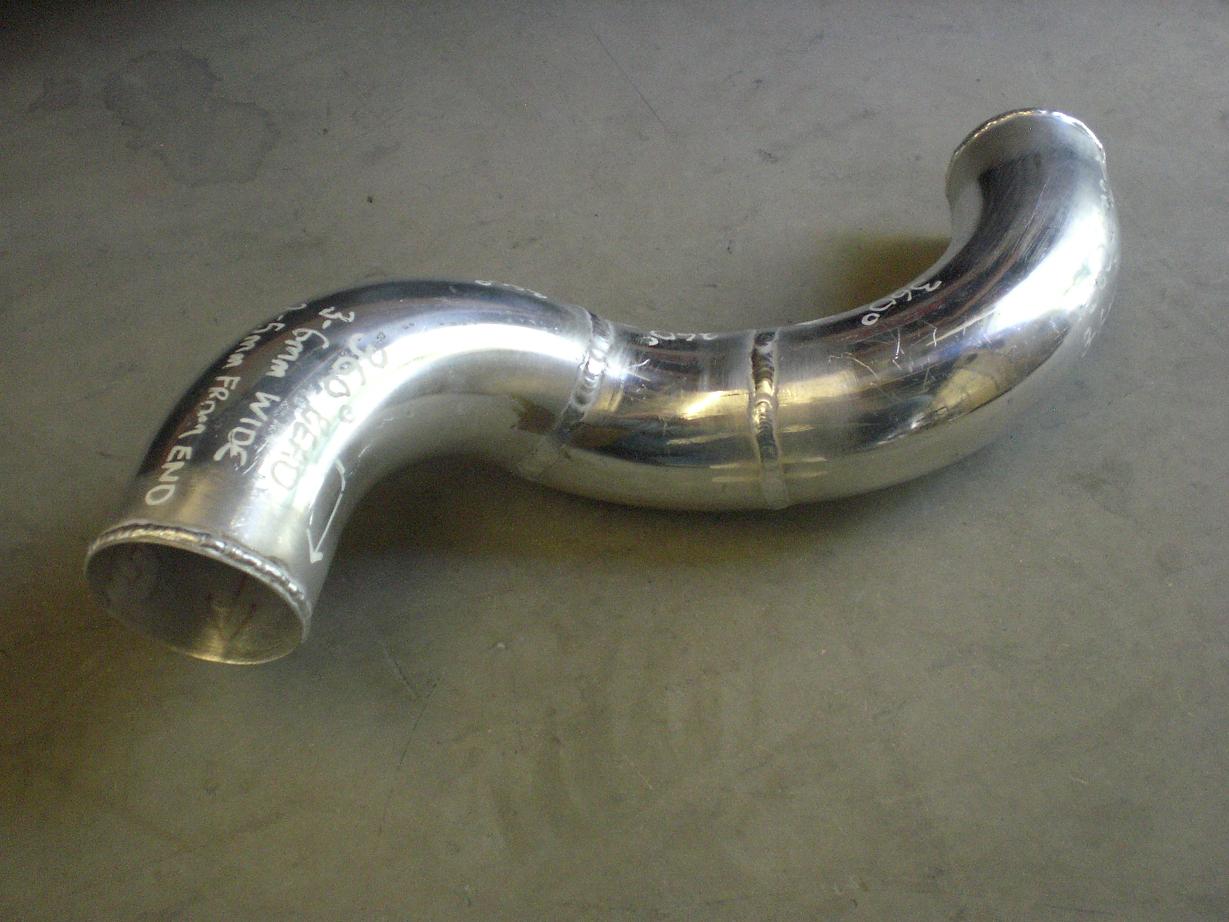
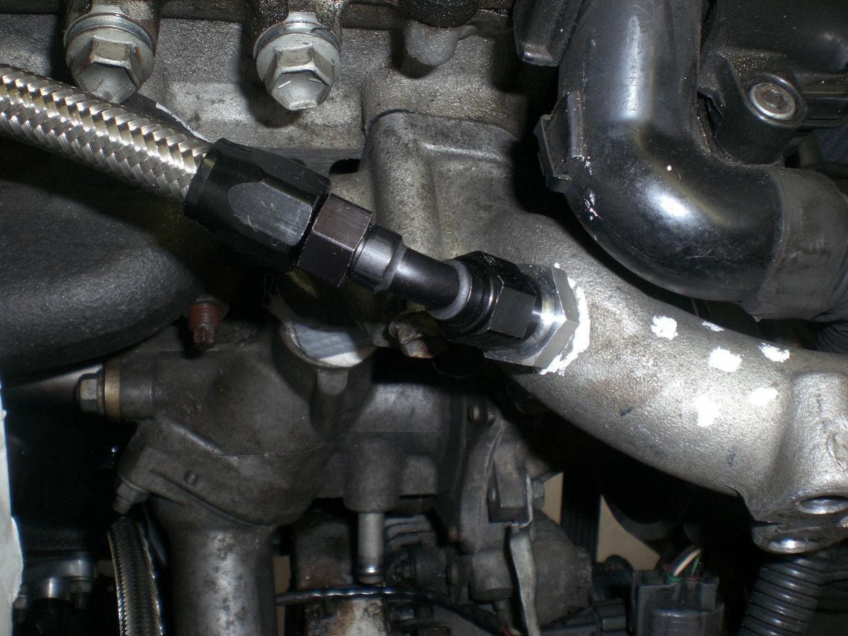
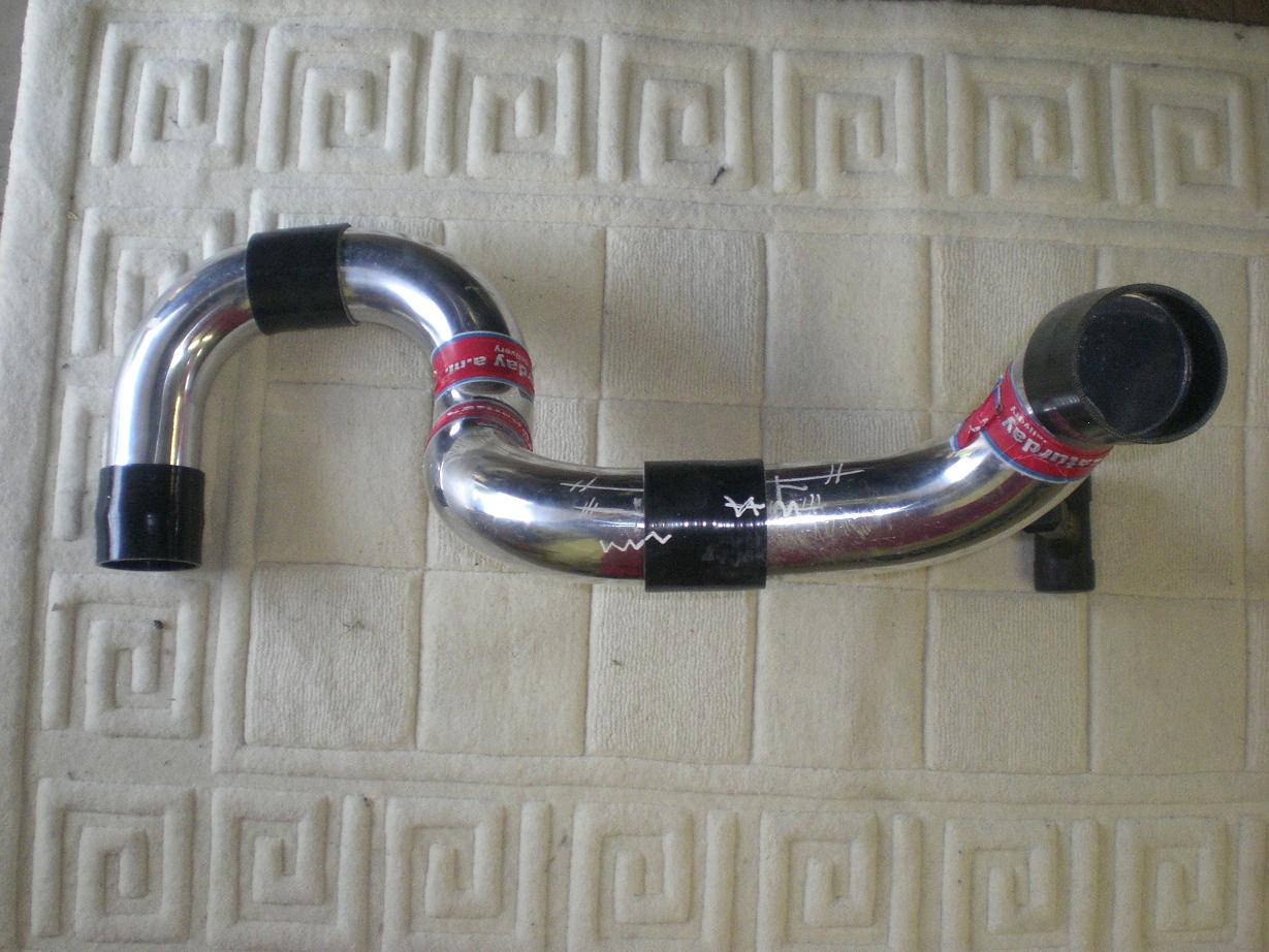
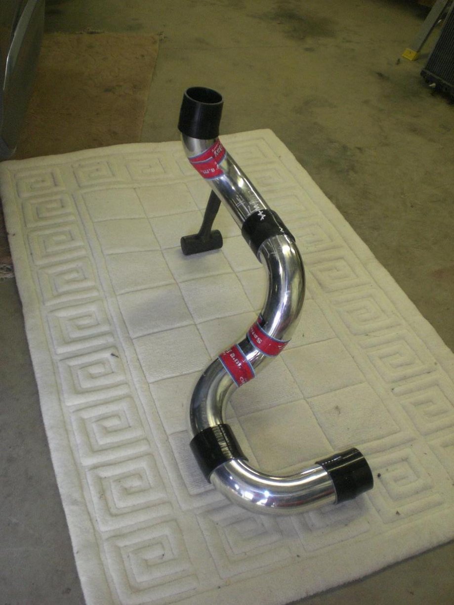
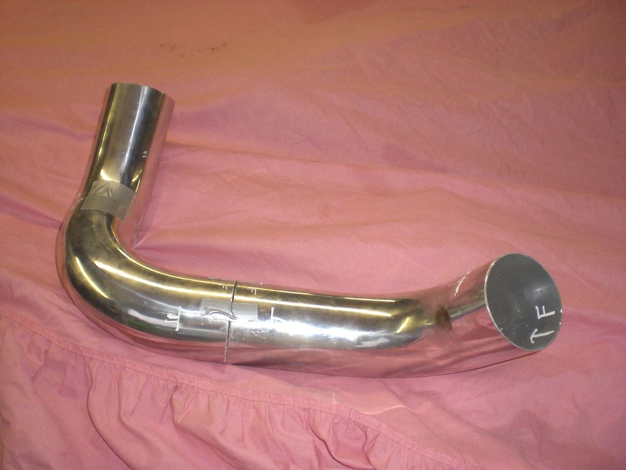
I originally schemed out all the intercooler piping with three or four silicon bends starting with a 45 degree off the turbo as you can see in the first pic. I was relatively happy with this but after looking at it for a day or two I decided it was actually a cr@p idea. So then I started again with more aluminium piping and set it all out so it only used straight silicon pieces (including the one of the compressor housing) for improved reliability. I ended up with a layout I was happy with....the black silicon hoses shown are in their correct places, the red tape is where the pipes need welding. Piping is 3" all the way from the compressor outlet to the throttle body and takes a nice route down past the alternator and bottom rad hose. This avoids the need for a 90 degree elbow on the turbo and all bends are steady and smooth for minimal pressure drop.


-
Is that your way of saying I'm a fussy git Darryl? I have a few pics of progress so far to post up so I will get those done over the next few days. I will try to keep a track of everything along the way and post up pics as I go as I'm sure there'll be a few interesting bits that people will want to see.
-
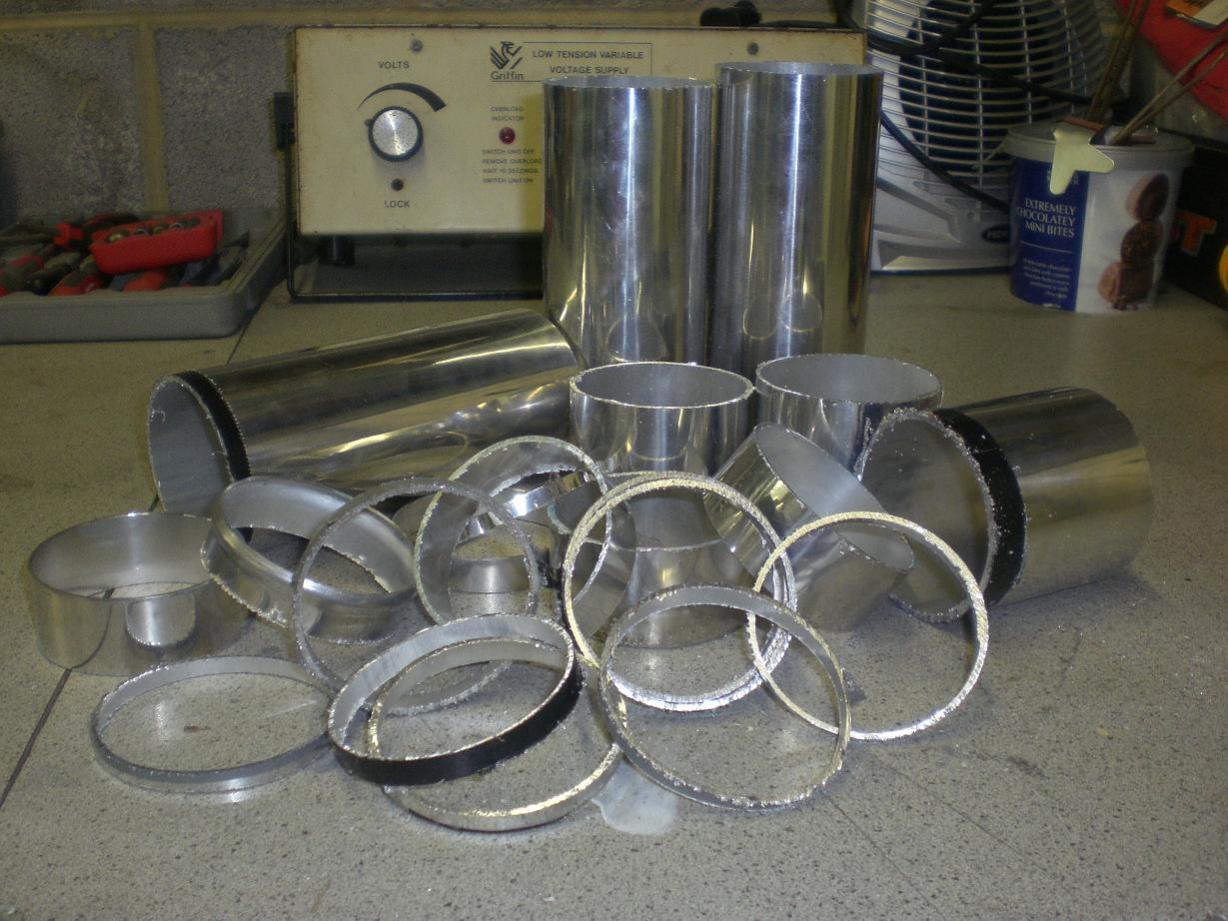
Here's a few shots of the intercooler piping being cut to the right kind of lengths and shapes for the routing to the intercooler.
-
At the moment I'm running no boost as she's in pieces off the road. On the original turbos I was running 1.1bar day to day, 1.2bar on occasion and i took them up to 1.3bar on the rolling road to check the fuelling was good. On the 67mm I'll be running around 1.4-1.5bar on the road with road fuel. Off the road....we'll have to wait and see