
dandan
-
Posts
4928 -
Joined
Content Type
Profiles
Forums
Store
Blogs
Events
Downloads
Supra Articles
Gallery
Everything posted by dandan
-
Cheers guys - hopefully I can press on a bit faster now. Things seem to have dragged a bit lately but the delay on the exhaust side did give me a chance to work on other things like the cam covers, intake, plenum etc so I suppose I haven't really lost any time. I'm waiting on a couple of 1.75" stainless bends to arrive now; with any luck they'll be here before the weekend so I can get the wastegate parts arranged properly before welding up the downpipe.
-
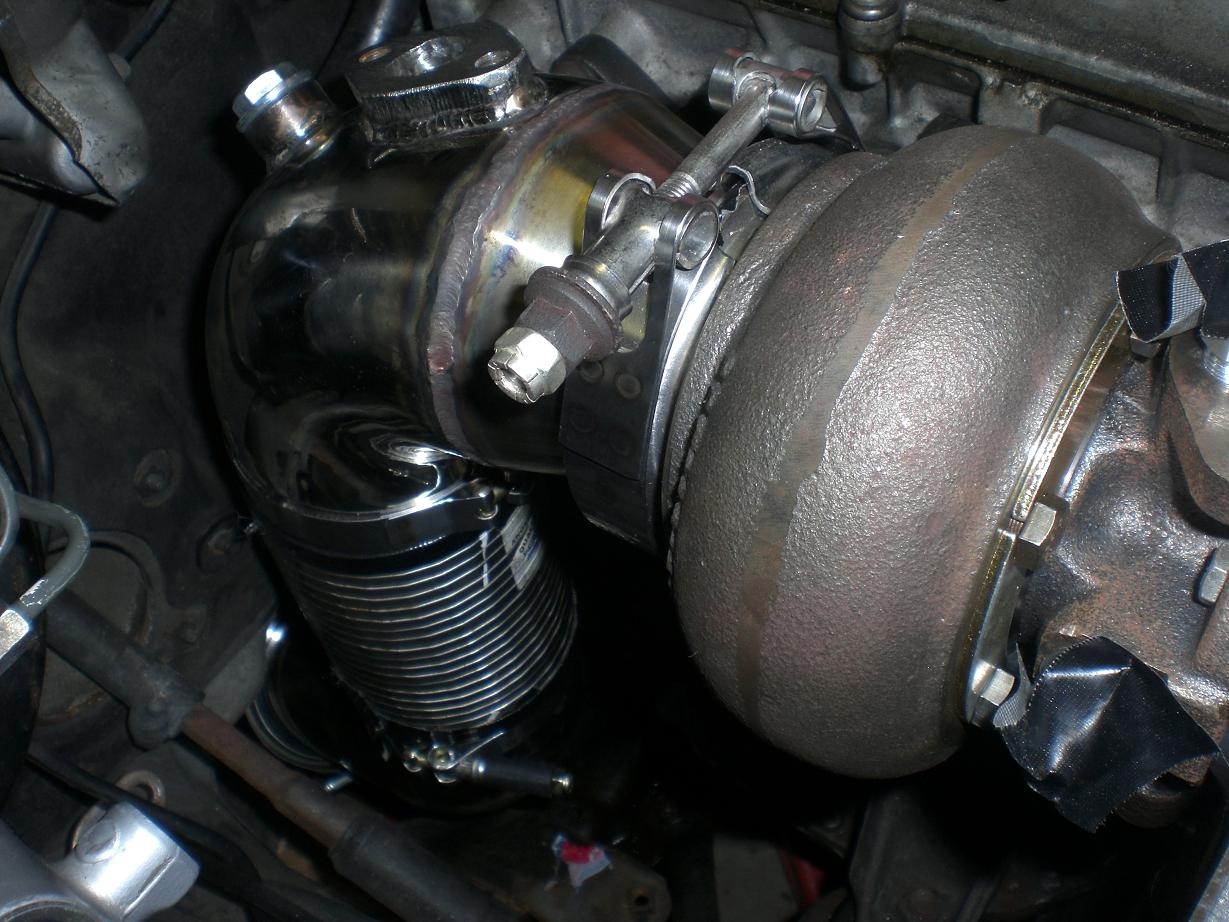
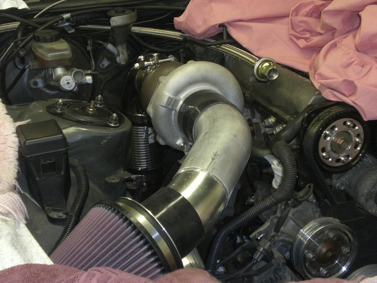
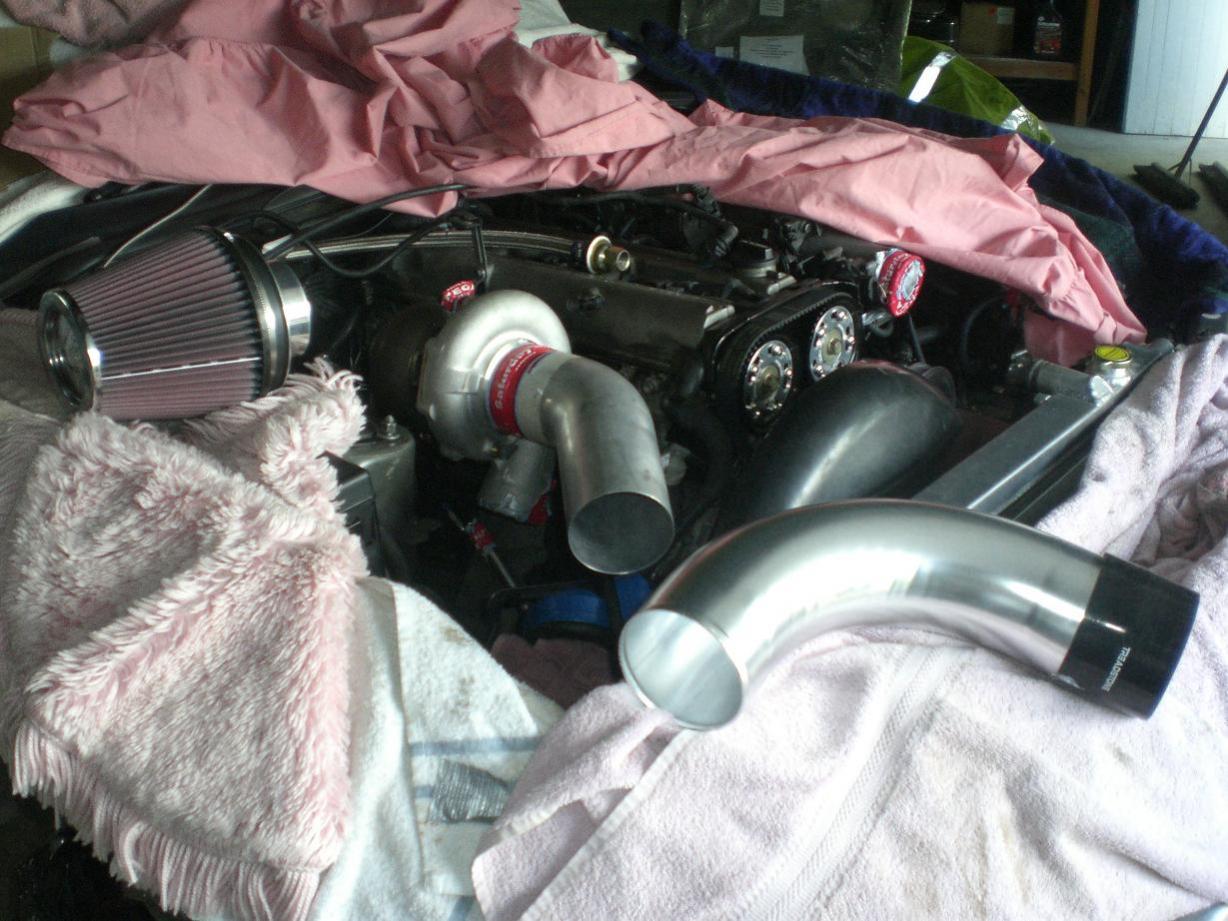
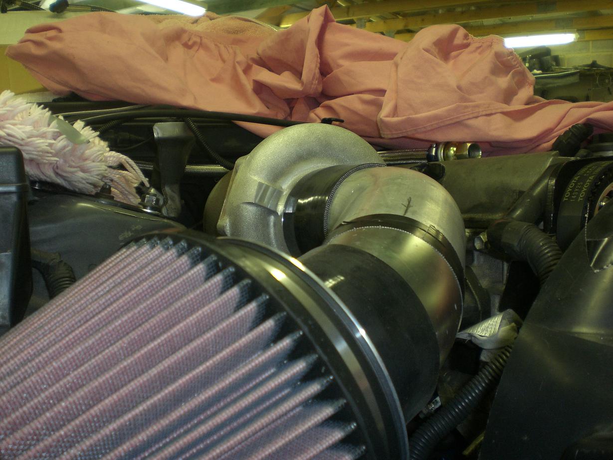
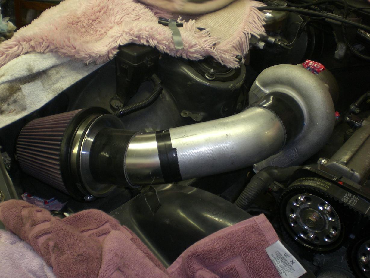
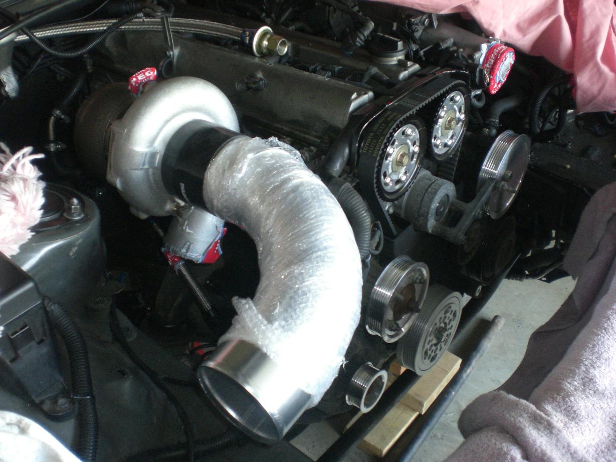
Here's a couple of shots of the general layout and positioning in the engine bay.... And this is how I left it tonight...........wastegate piping to be tackled at the weekend!
-
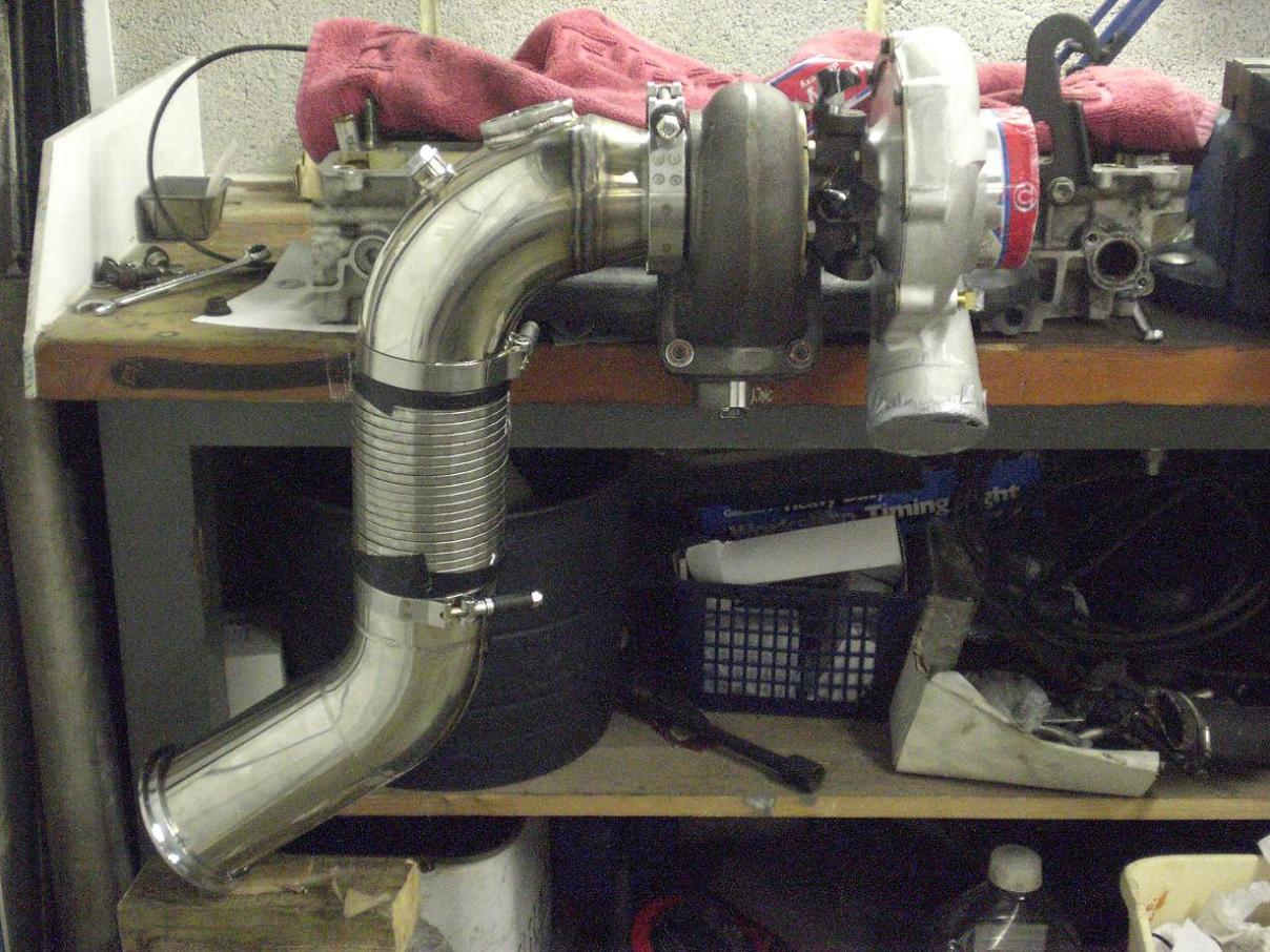
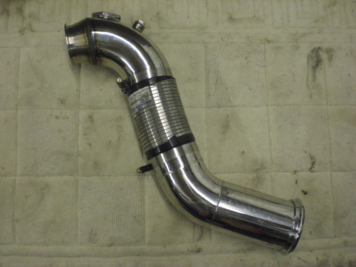
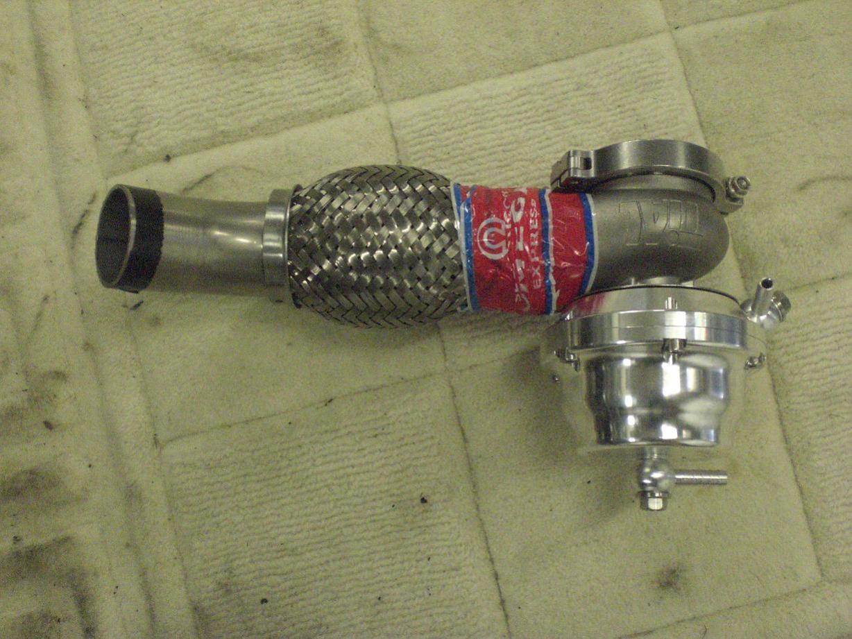
I wanted a flex in this downpipe and whatever happens I will get one in. It makes life a lot easier in some ways (an extra bit of freedom for alignment, allowance for expansion, isolating exhaust movement from the turbo/manifold) but also adds some complications...it's another thing to weld in, it takes up space, it means the downpipe needs more support to hold the midpipe in a sensible position etc etc. Plus they are not easy to find in 4" without being 12" longl! Now I have three different types I ordered lots to make sure I'd have something that worked. The lowest profile one I have found is a Dinex spiral flex. This is stainless, low profile, and has good flexibility. I will probably end up going with this as it has the smallest OD of all of the ones I have, giving the greatest clearance. The downpipe will be braced below the flex so it will never be under tension....all it has to do it take care of thermal expansion issues. This is justa mockup to allow to check clearances etc. (Ignore the tape and clamps!)
-
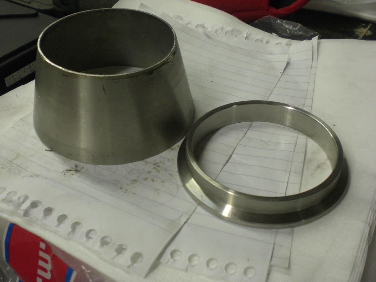
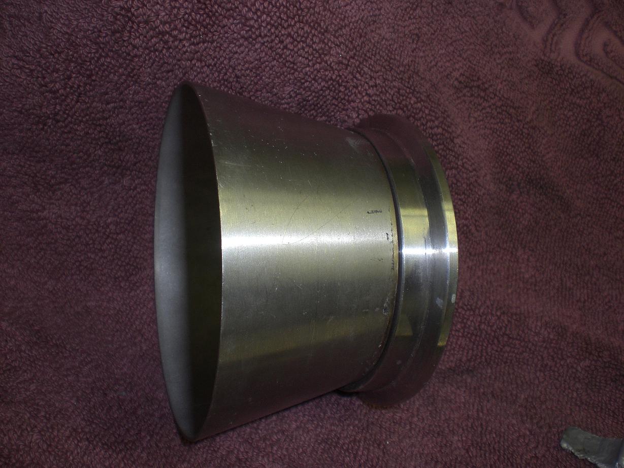
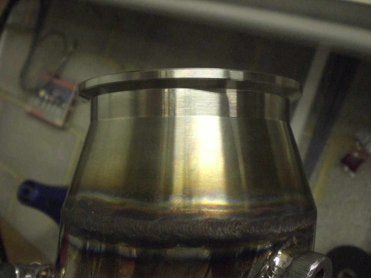
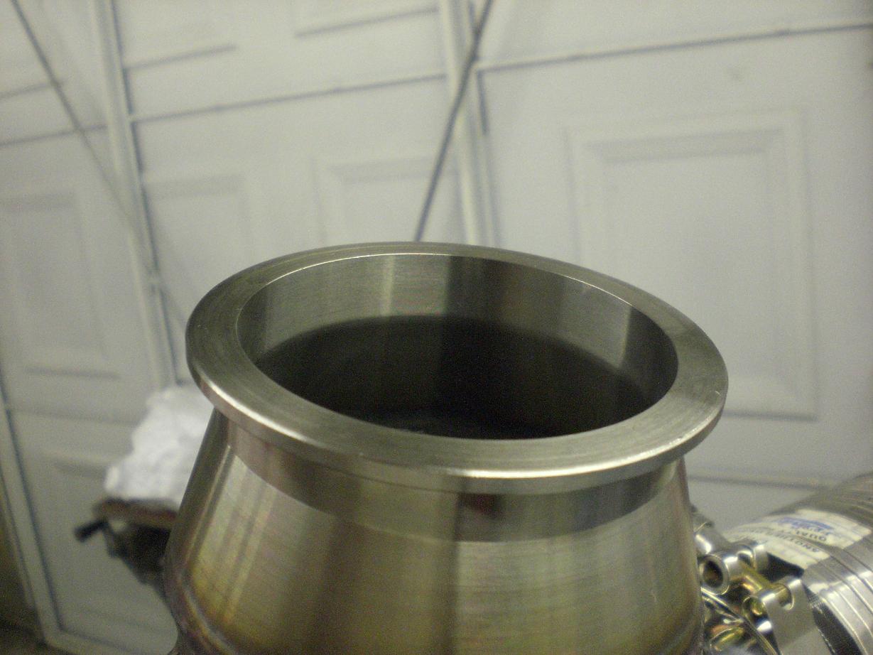
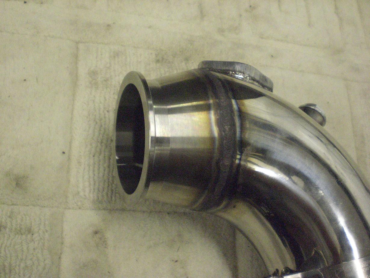
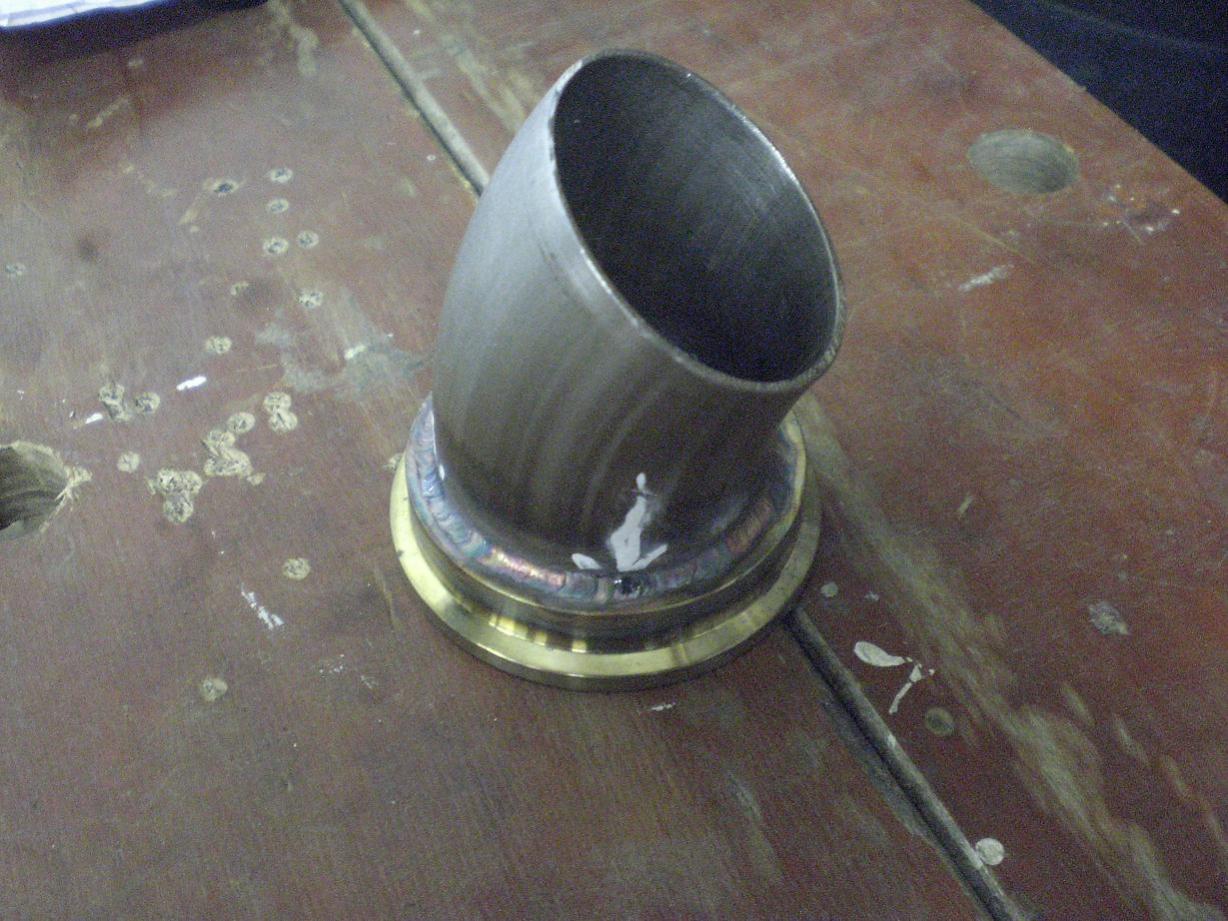
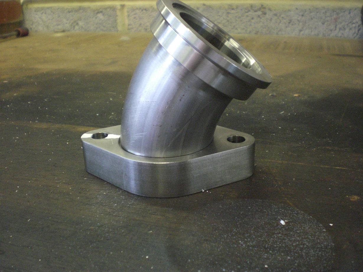
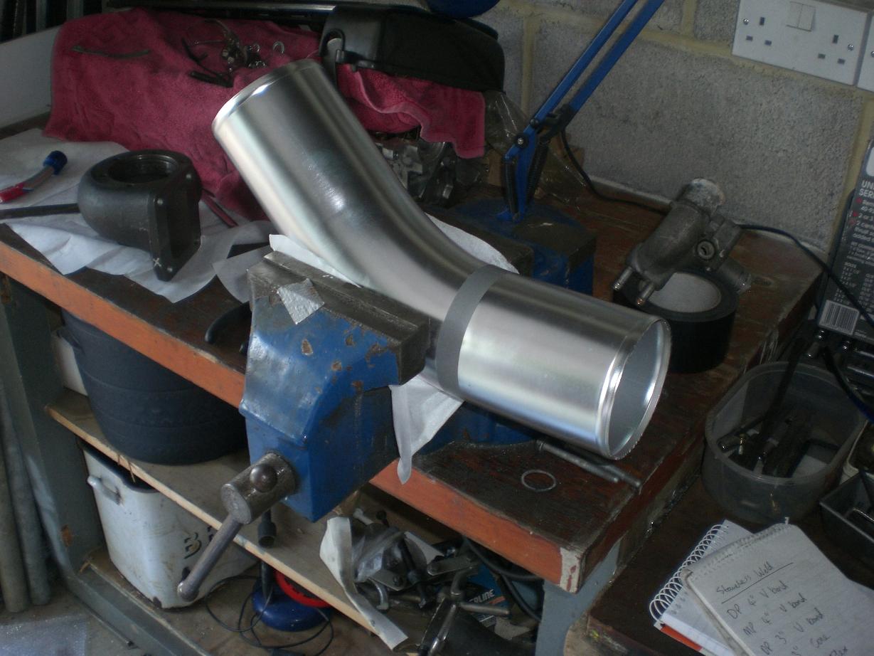
One of my main hold ups has been the downpipe. I can't fnish anything on the wastegate, midpipe, catch tank or breathers until the downpipe is finished....that way I know what room I have to play with. I had it pretty much sorted but I wasn't happy with how close it was to the bulkhead or clutch master cylinder. The cast manifold doesn't have a clocked turbo flange so the downpipie sits aligned with the engine pointing almost directly at the clutch master cylinder. A transition from the 3" V band up to 4" pipe means the 90 degree turn is close to the master cylinder. I had a complete new V band flange and transition to 4" machined from solid -this saved messing around with welding and got the exact profile I wanted. Now there's lots of room, the internal transition is smooth and I'm able to start back on it and make some progress These are the pieces I managed to find and these were a last resort....the downpipe would be a little too close too the master cylinder if I used these (probably ok but I wasn't completely comfortable with it) So, like I said, I went with a custom piece from solid and that got me just what I wanted:
-
Is anyone here running a none stock intake temp sensor? I have been looking for a Delco one but the only place I have found that has them is Owen Developments. Does anyone else have one or could anyone point me in the direction of where else I might find one? FYI - The sensor at Owen Developments is approx £65 +VAT and shipping. I'm curious if they are available for less money elsewhere before I buy this one. Cheers Dan
-
Spot on Kev - thank you. All in £49.68 inc vat and £2.50 delivery.
-
Sold.
-
I'll get a few photos tomorrow night Paul with the gasket against mine and the gasket against the head. From memory it was pretty damn good as it was. The head mating face was flat to within about 6 or 7 thou as well. Not bad. The T4 outlet shape left a bit to be desired and the wastegate port was small. In general I am very impressed.
-
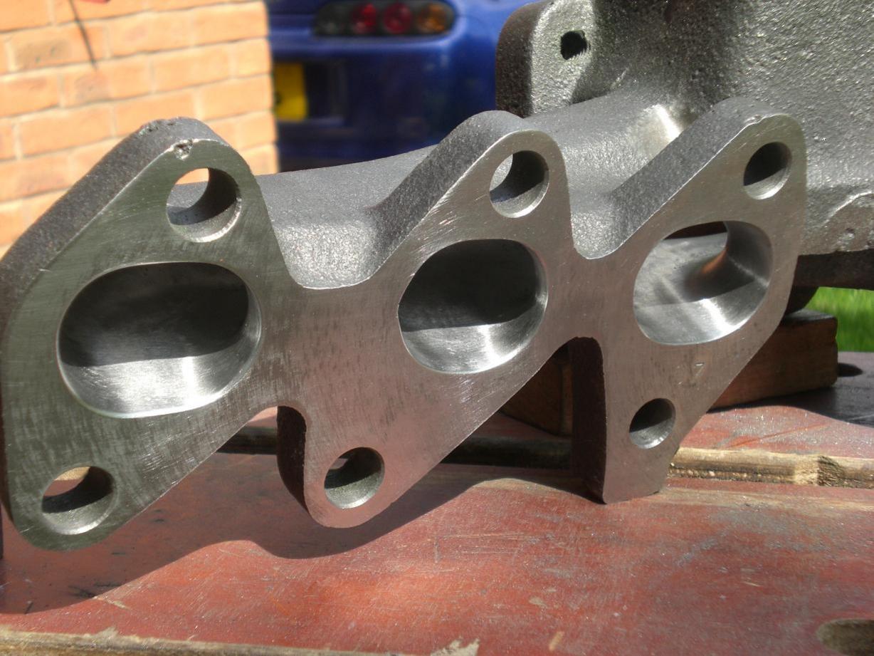
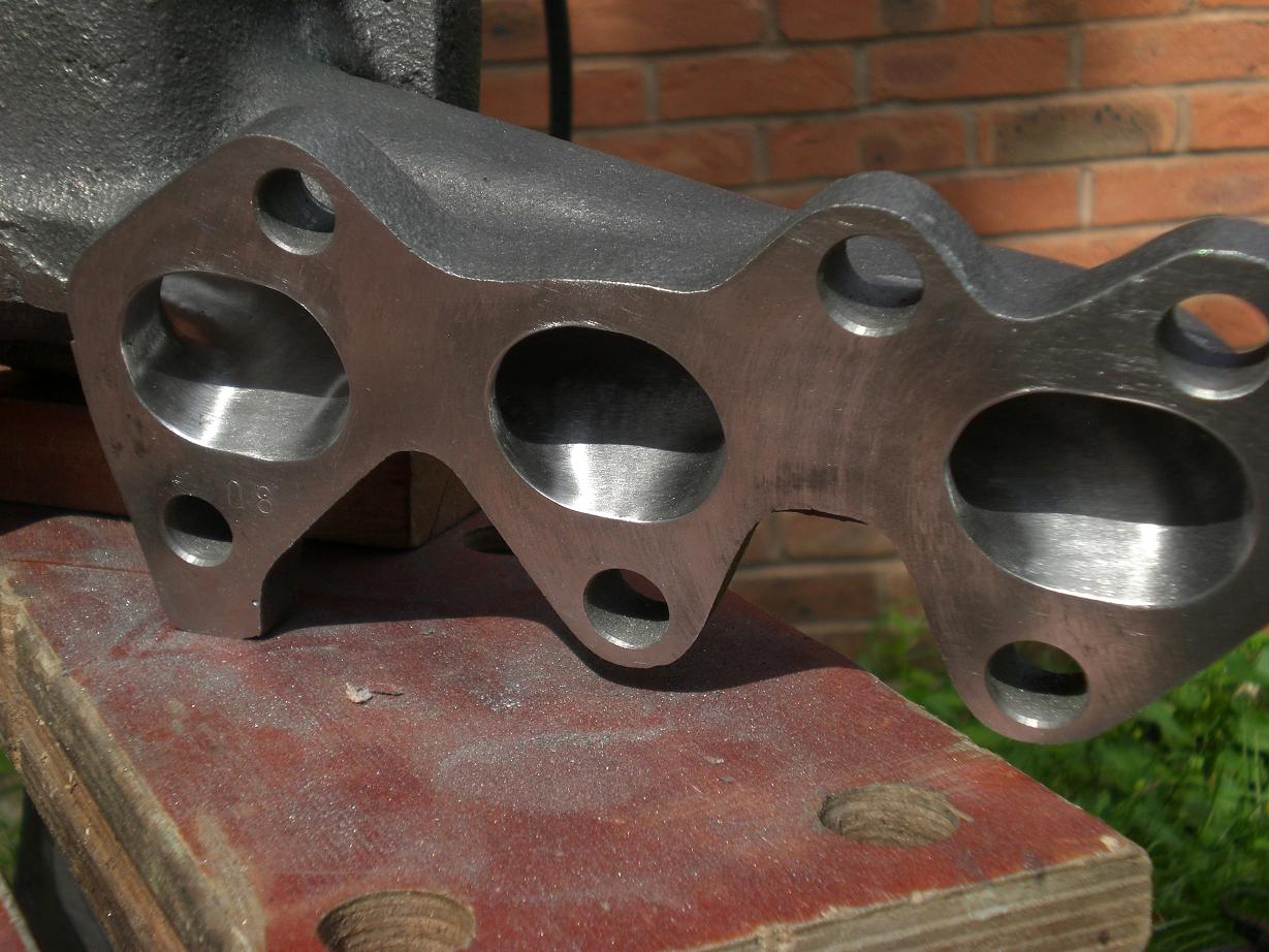
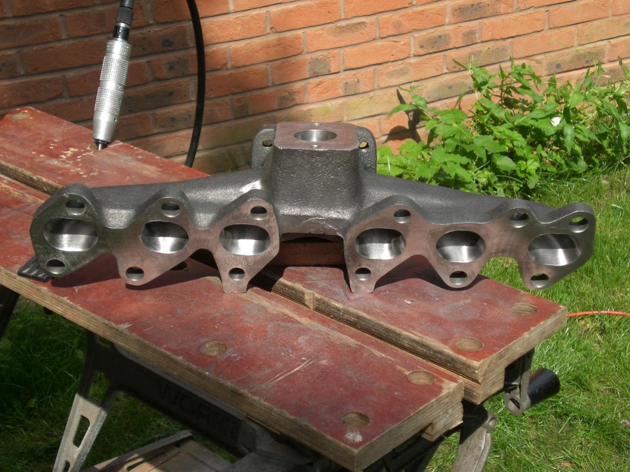
I spent some more time finishing the manifold porting. Now it's pretty much ready to go for ceramic coating. I am going to wait until I have the downpipe, midpipe, and wastegate pipework ready and then send it all in one go with the manifold and turbine housings.
-
-
Good stuff Paul - keep up the good work. Like Darryl said - it's nice to see people trying new things. Any chance you could email me a few decent pics of the inside of the cast manifold? (I want some baseline pics to compare mne to)
-
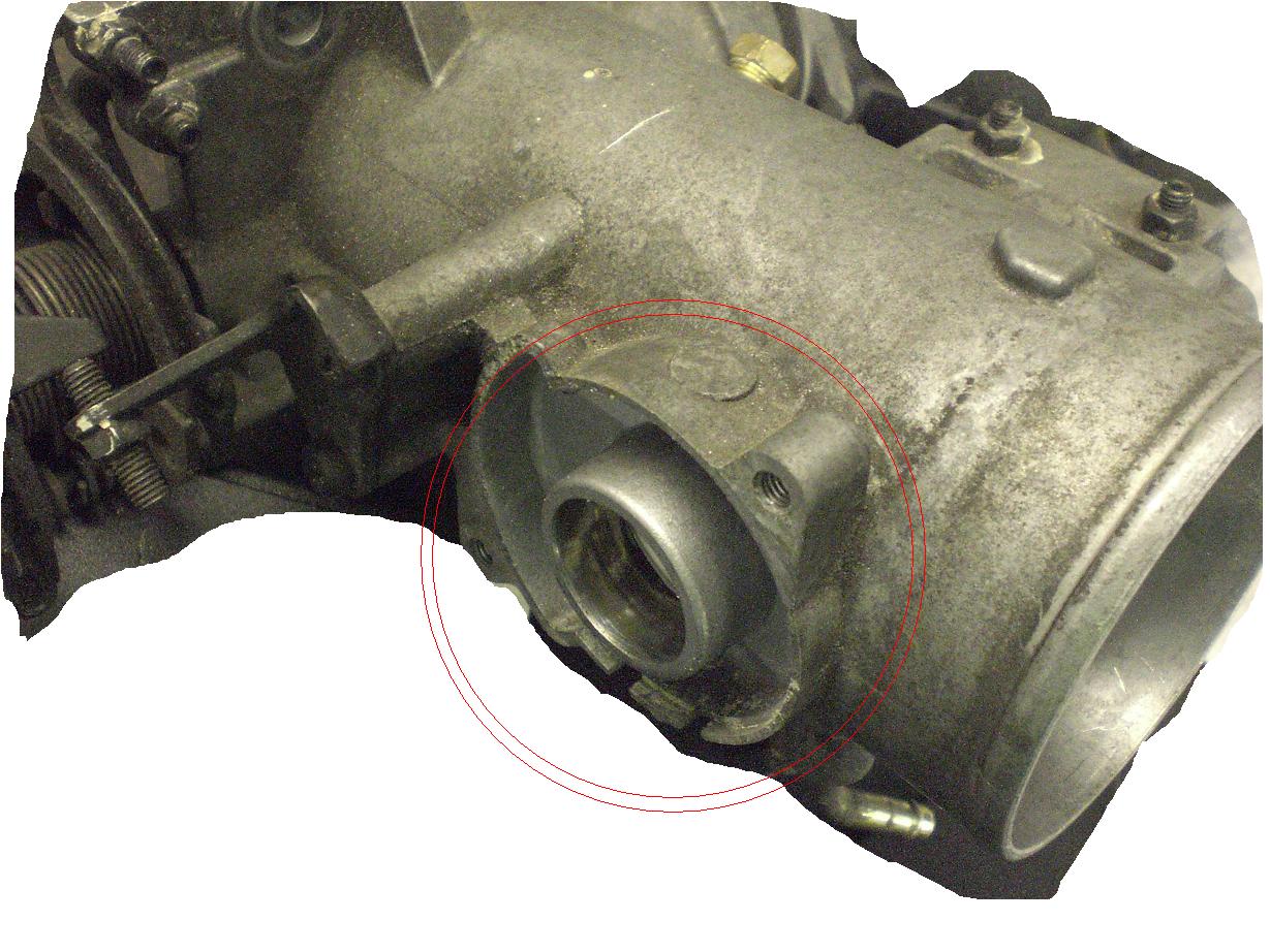
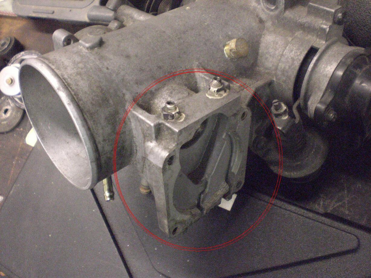
I've had no butterfly in there for quite some time and seen as I'm fitting a replacement body I figured I might as well tidy it up a bit and get rid of all that crap on the outside. It will hopefully make for a better water injection spray as well as the water won't impinge on the (redundant) spindle.
-
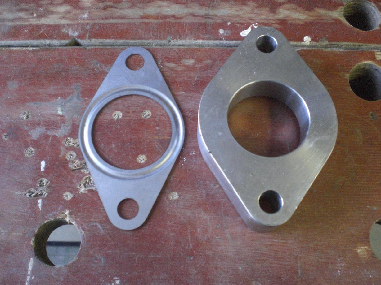
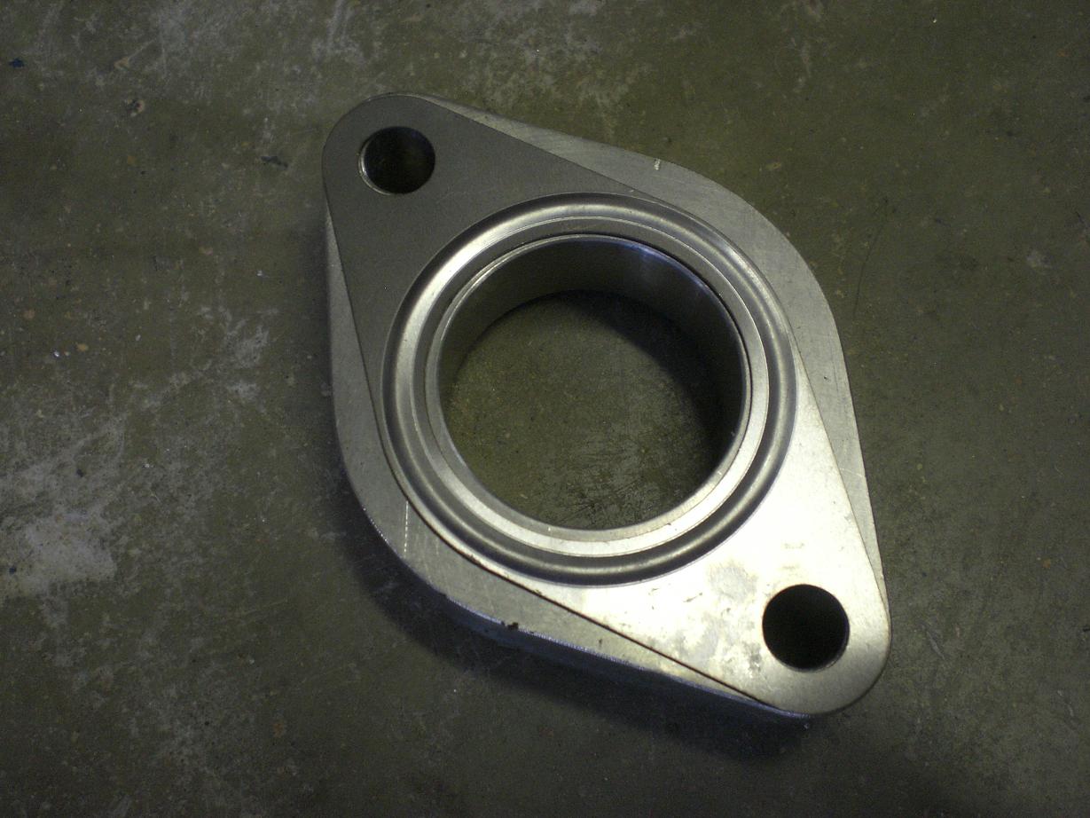
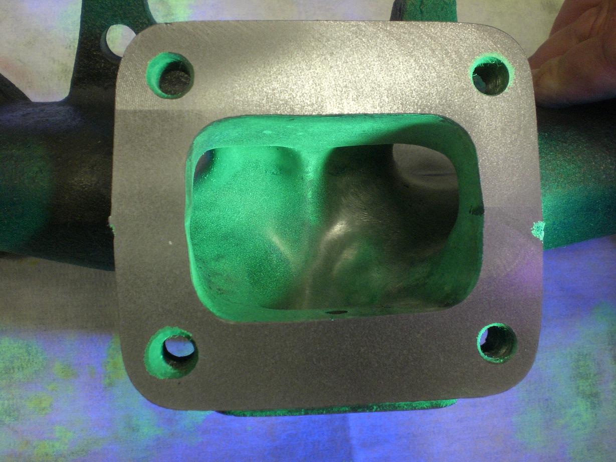
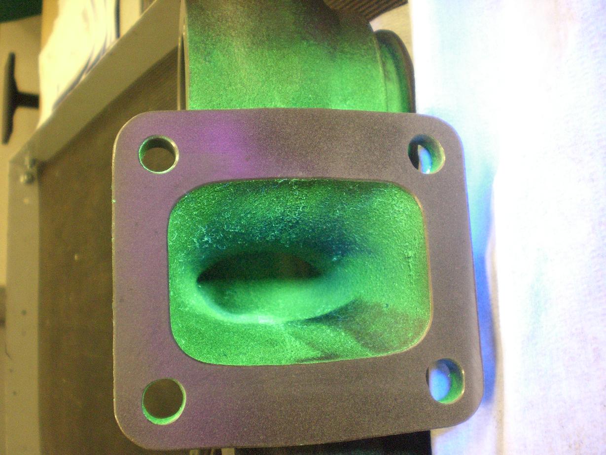
Here are a few shots of the wastegate parts I have been mocking up. I'm waiting for a piece for the downpipe to arrive before I get the wastegate feed finalized. If I was running a screamer pipe I could simply press on but I'm recirculating the wastegate outlet so I need the downpipe finished and in postion before committing to the arrangement for the wastegate plumbing. I have shown a shot of the flange vs. a normal Tial 38mm gasket. This was taken before the centre hole was enlarged. This gives an idea of how much extra material can be removed from the wastegate/manifold flange whilst maintaining a decent sealing area. I will be running with no gasket and the surfaces will be machined flat after all welding is complete.
-
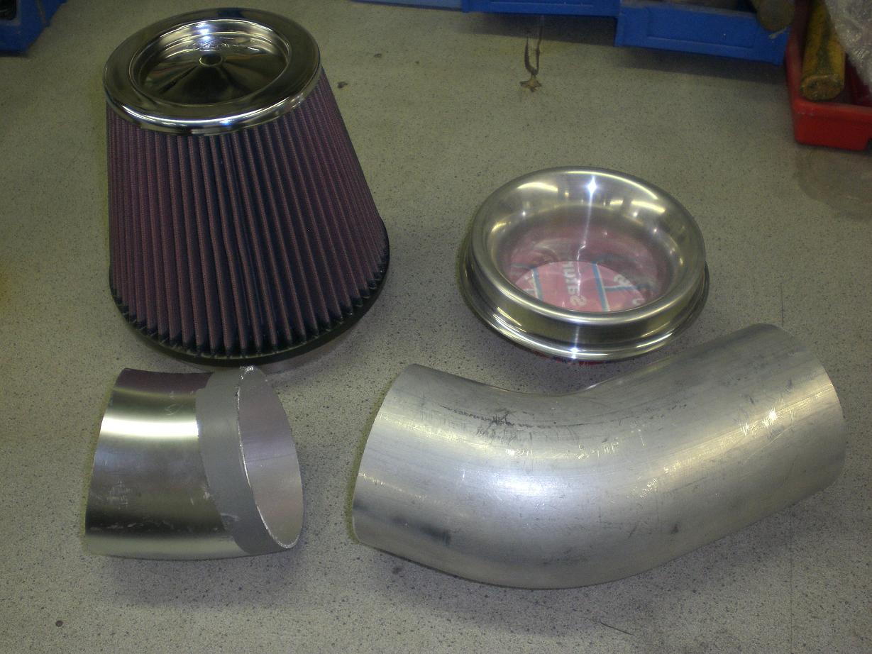
Making up the intake pipe followed a similar pattern to the intercooler piping.... - Buying enough tube pieces to cut to required shape and lengths - Lots of hacksaw and file action - Matching curves and mocking up the final design prior to welding The parts are now with the welder along with a couple of other little bits. I tried a 90 degree piece to start with to see where that would put the fiter but it simply didn't fit. It seems a shame to cut up a decent 45 degree 4" pipe just to get a 20degree or so bend out of it but nevermind! Once all this is complete I will scheme up a sealed airbox and feed from the old intercooler duct. That should allow plenty cool air to be drawn in without exposing the filter to any muck/debris on the road if I tuck it down in the side duct area.
-
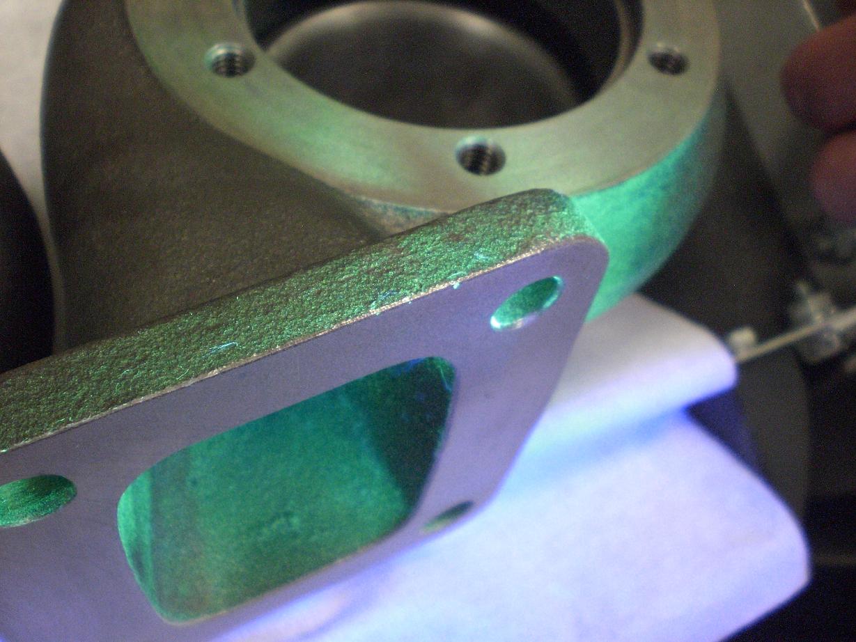
A few more pics of the manifold and turbine housings during crack testing....thankfully no cracks.
-
Nope I only want to do it once so am doing my best to make sure there are no balls ups along the way!
-
How much are you after with postage then mate, looks like it'll suit me fine
-
Aha - interesting
-
OK guys.... Can I simply chop off and grind down all of the casting around the trac butterly areas to tidy up the throttle body? Can the throttle body be welded like any other piece of aluminium or is it some strange oddball material. I would need to get the trac butterfly spindle holes welded up as well as the tapped hole for the brass bung you an see. What's the verdict? Cheers Dan
-

group buy Uprated ally Radiator Expansion Tank
dandan replied to johnd-mkiv's topic in Parts for Sale
OK spot on - thanks John. -
for sale 1995 N/A Manual Supra with LSD in Green
dandan replied to Clinton's topic in Supra Classifieds
Nice car - paintwork looks excellent. -
Happy birthday Matt.
-
Does anyone have one? I only need it to cut the flange off the end! Cheers Dan
-
for sale Tial 44 mm Wastegate, Vband Screamer pipe, Heckler Resistor pack
dandan replied to RobSheffield's topic in Parts for Sale
Ball bags! -
Can anyone get me a Tial outlet flange (V band) and a clamp? Cheers Dan


