dandan
-
Posts
4928 -
Joined
Content Type
Profiles
Forums
Store
Blogs
Events
Downloads
Supra Articles
Gallery
Everything posted by dandan
-
More than your old motor?
-
I'm sure I have one - used but fine. I took it off as it looked grubby but in the end I bought a new one as I couldn't be bothered to clean it up and paint it! I'll take a look tomorrow.
-
Cheers Kev. The heatshield is made from Nimbus GII material. It is available from Demontweeks here: http://www.demon-tweeks.co.uk/products/ProductDetail.asp?cls=MSPORT&pcode=NIMG2C There is a thinner version (more like 3mm total thickness tather than my stuff which I think is about 5mm) and that is called G1 or Nimbus Light I think. Edit: This stuff on Ebay looks almost identical too: http://cgi.ebay.co.uk/HEAT-SHIELD-HEAT-BARRIER-MATERIAL-1200mm-x-615mm-approx_W0QQitemZ170403211216QQcmdZViewItemQQptZUK_CarsParts_Vehicles_CarParts_SM?hash=item27acd2a7d0
-
Thanks Mig Ryan is coming out tomorrow to fit the Solaris, and get a map setup so I can give it a bit of a shakedown for a good week or so. It's pretty much finished now, the only real jobs left to do (barring the longer term stuff like the Greddy intake and huge front mount intercooler) are: 1. Finish and fit the airbox 2. Complete the fitting of the Aquamist 2S water injection system (needs a tank fabricated to fit in the boot where the tools reside) 3. Fit the breather tank, valves and pipework to the exhaust (no flexible hardpipe in UK at the moment apparently so that's on hold for a couple of weeks) 4. Electric exhaust bypass valve (for dumping the exhaust gas after only one silencer, rather than three)
-
We need a couple of live web cam feeds from SRR
-
Good luck to everyone for tomorrow, hope you all get the sort of numbers you're after and all goes well.
-
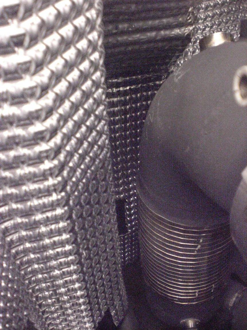
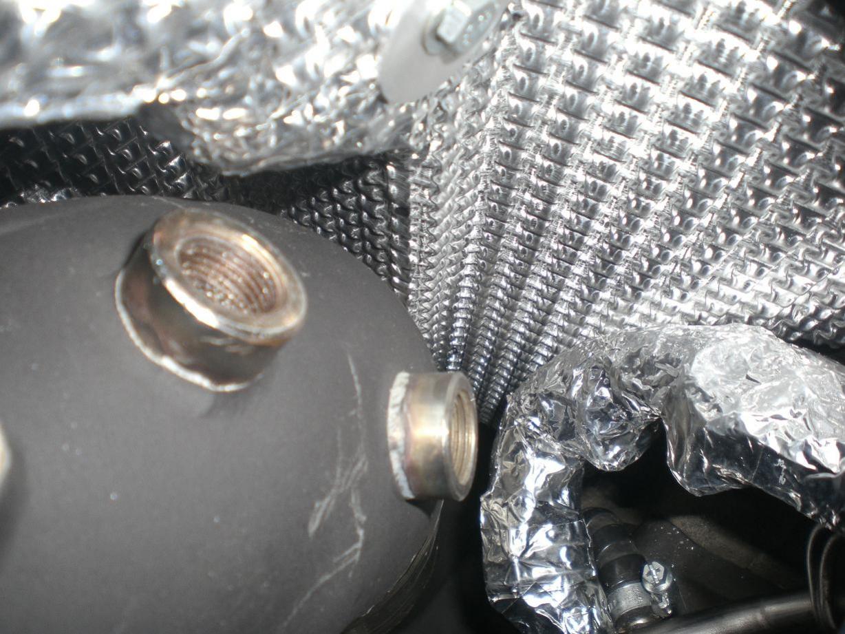
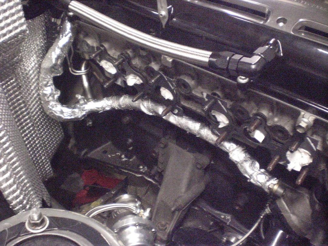
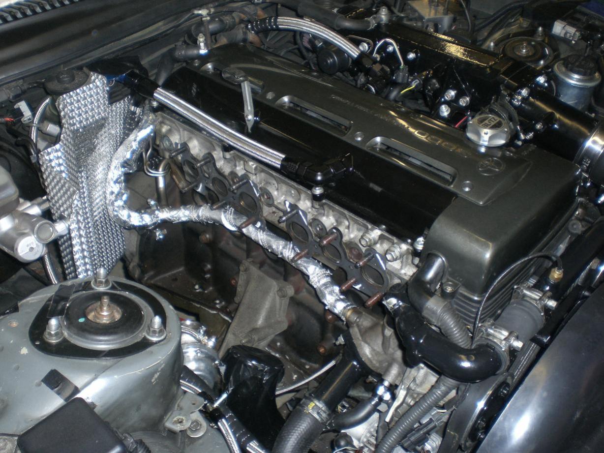
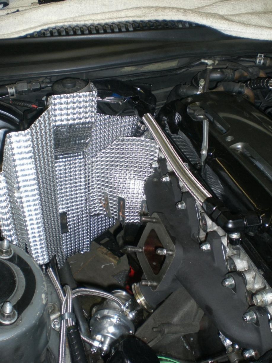
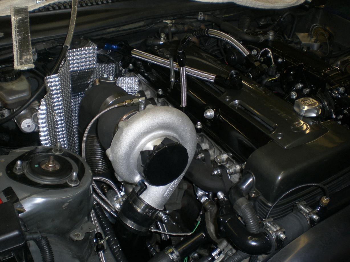
As I mentioned earlier, all the exhaust side parts were ceramic coated to help cut down heat rejection to the engine bay and other components. I still needed some sort of heat shielding for the clutch master cylinder so I knocked this up... It's a close fit to the master cylinder, brake servo, inner wing and bulkhead to maximize room around the downpipe. It took a bit of sorting but turned out pretty good. I also wrapped the solid and flexible water pipe with some reflective asbestos style matting and then added further reflective wrap to the flexible hose at the back of the engine bay. Then to be 100% sure I'd done all I could I added a small additional heat shield to further protect the flexible water hose. I’m a big fan of minimizing the load on the cooling system so given that the turbo is water cooled I’ve done whatever I can elsewhere to help out. This is how it looks now with only a few jobs to finish before Ryan comes to put a "shakedown map" in the ecu for me on Monday:
-
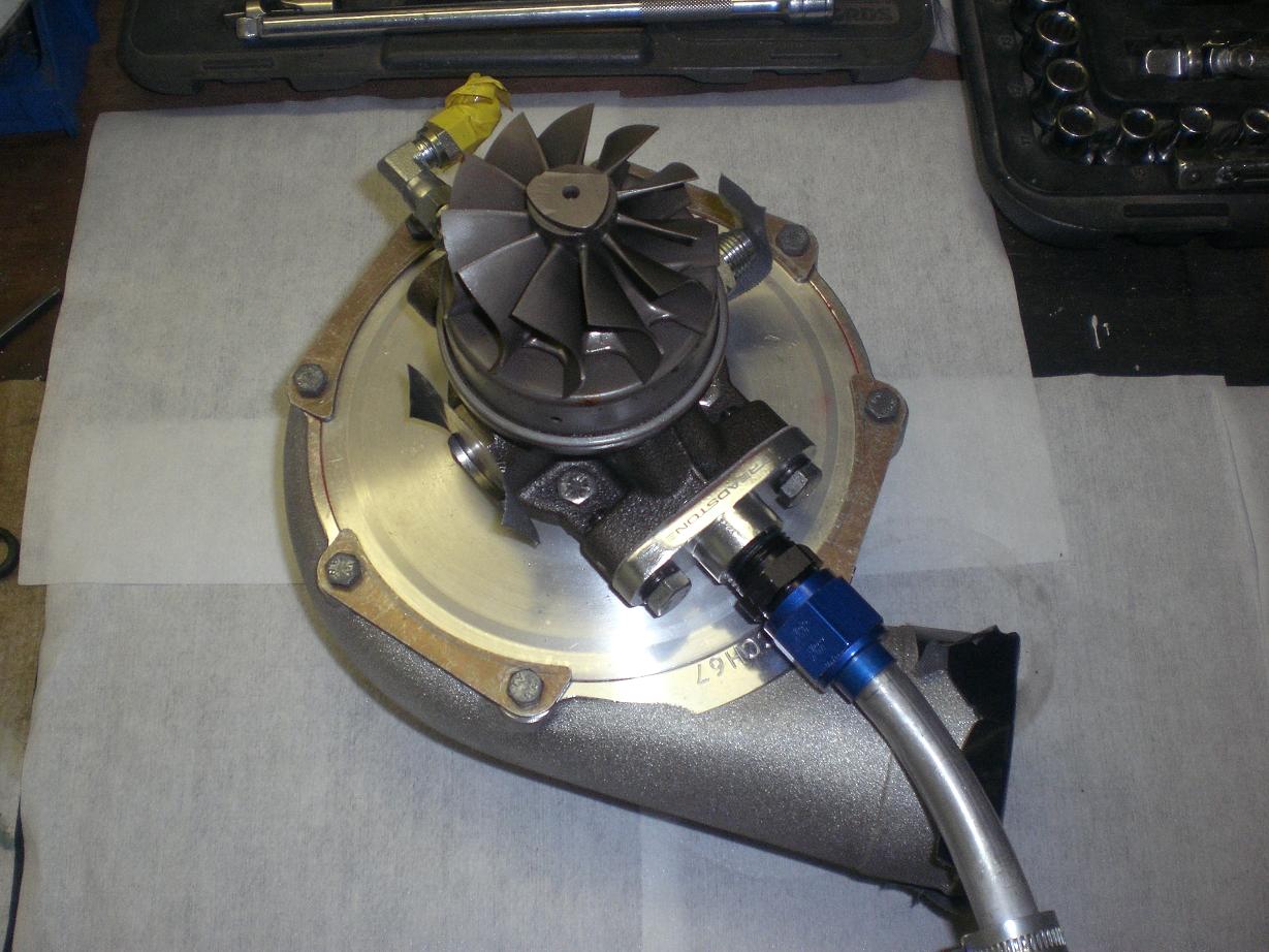
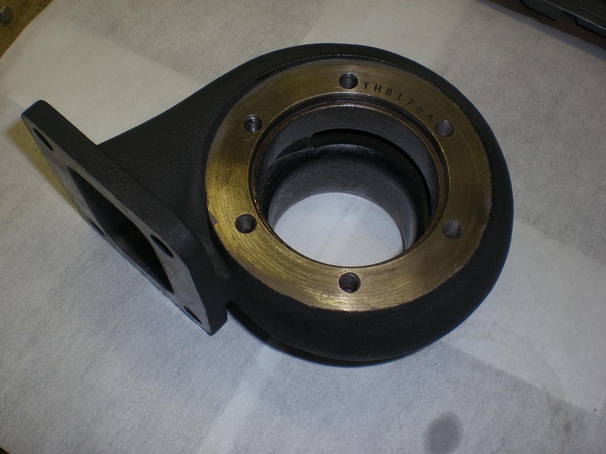
The turbo need some quick assembly work to put the 0.81 housing back on after sending it to Zircotec for the ceramic coating...nothing major.
-
Cheers Jamie - performance should be interesting as I don't think anyone else has an identical spec to compare to. Done. NASA spec! LOL This was one area I definitely wanted to be 100% confident in. Now I don't ever have to wonder how things look in there in terms of cable ties, heatshrink, chocolate blocks etc. Fit and forget. Thanks Mark, always nice to get some positive feedback. Sorry to hear about your's mate - terrible news. Hopefully this thread will help give people some ideas and also an appreciation that paying attention to details is just a question of time and patience really. Thanks a lot Mig, appreciate it mate. Like I said, for me it is just time and patience. I don't think anything has been "above normal" in terms of attention to detail - anything like this I do is always to this sort of standard as it seems normal; anything less would feel like a bit of a bodge I've been away for a couple of weeks but I'll get a few progress photos up for you picture hungry fellas
-
Looks lovely, well done to you and Lee. How's the traction with the Falken tyres? Oh yeah, seen as I won't be there on Sunday I'm gonna throw a crazy guess into the mix of [email protected].
-

group buy Uprated ally Radiator Expansion Tank
dandan replied to johnd-mkiv's topic in Parts for Sale
Good man I'm trying to think of the best way to describe that bracket, hopefully it's self explanatory.... If you let the cardboard piece hinge back down so it sits horizontal...ideally its top face wants to be completely flush with the top face of the tank and made from the same thickness material. That will run onto the top of the inner wing and I'll drill a suitable mounting hole through once I have the postion perfect. The tank will sit about 10mm from the inner wing so there's loads of room underneath that bracket (by the yellow tape) for a big fillet of weld especially if you think a "smoothed" weld on the top won't be strong enough. Make sense? -
Very nice....that turbo and your new cams must be very well matched.
-
Hellfire! What fuel did you have in there? Do you have numbers for a lowly 1.4 or 1.5bar run for comparison to your old ones?
-
Very nice What boost did you go up to Jamie?
-
Ooh you've got me thinking now!
-
Keron - you never did send me the undertray and centre console pic
-
group buy Uprated ally Radiator Expansion Tank
dandan replied to johnd-mkiv's topic in Parts for Sale
Can I get a bundle price? The other tank will be headed back to you today mate - looks spot on. I have also taped on a cardboard mount too and have some photos in case it gets ripped off in the post. -
Nice - what's the plan...road fuel only?
-
I'm in for updates on delivery date
-
Homer - you can take me off the "maybe attending" list too mate...I'm not sure if there's a limit on attendees but that may free up a space for someone else who does want to come along.
-
Do you have the nuts?
-
Can anyone tell me how much a front top suspension arm weighs please? Thanks Dan
-
Cheers Wes, That's it now for two weeks as I away for a little while. As soon as I get back I'll crack straight on with it again as I'm really close to being back on the road now. I should be able to get all the turbo side fitted easily in one evening and then I'm ready for the Solaris and the mapping. I'll probably crack on with the water injection install and finishing off all my heatshielding too in the time until Ryan comes over to install the ECU...hopefully that won't be too far away as I'm itching to get it on the rollers and back on the road
-
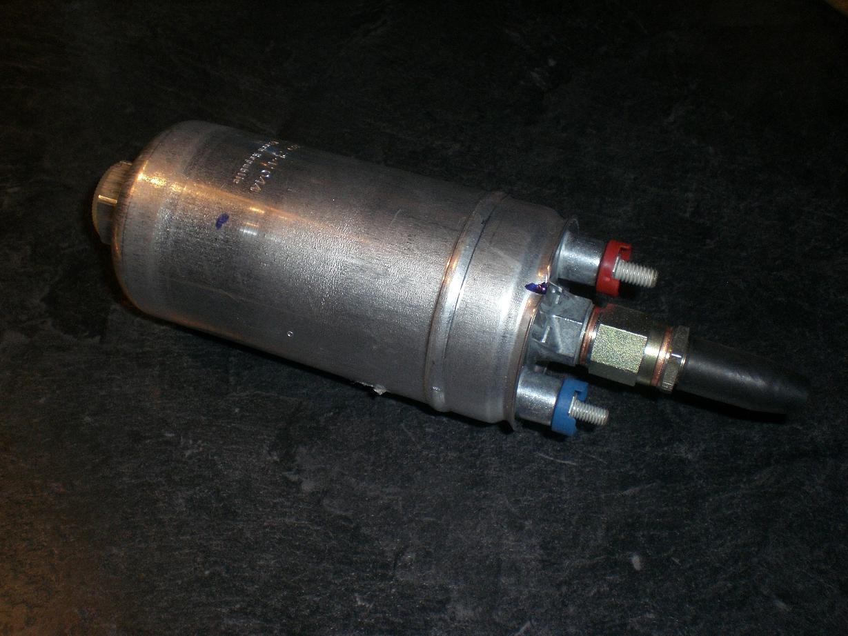
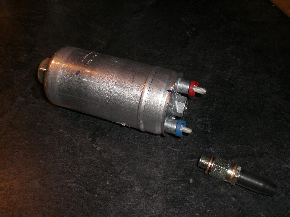
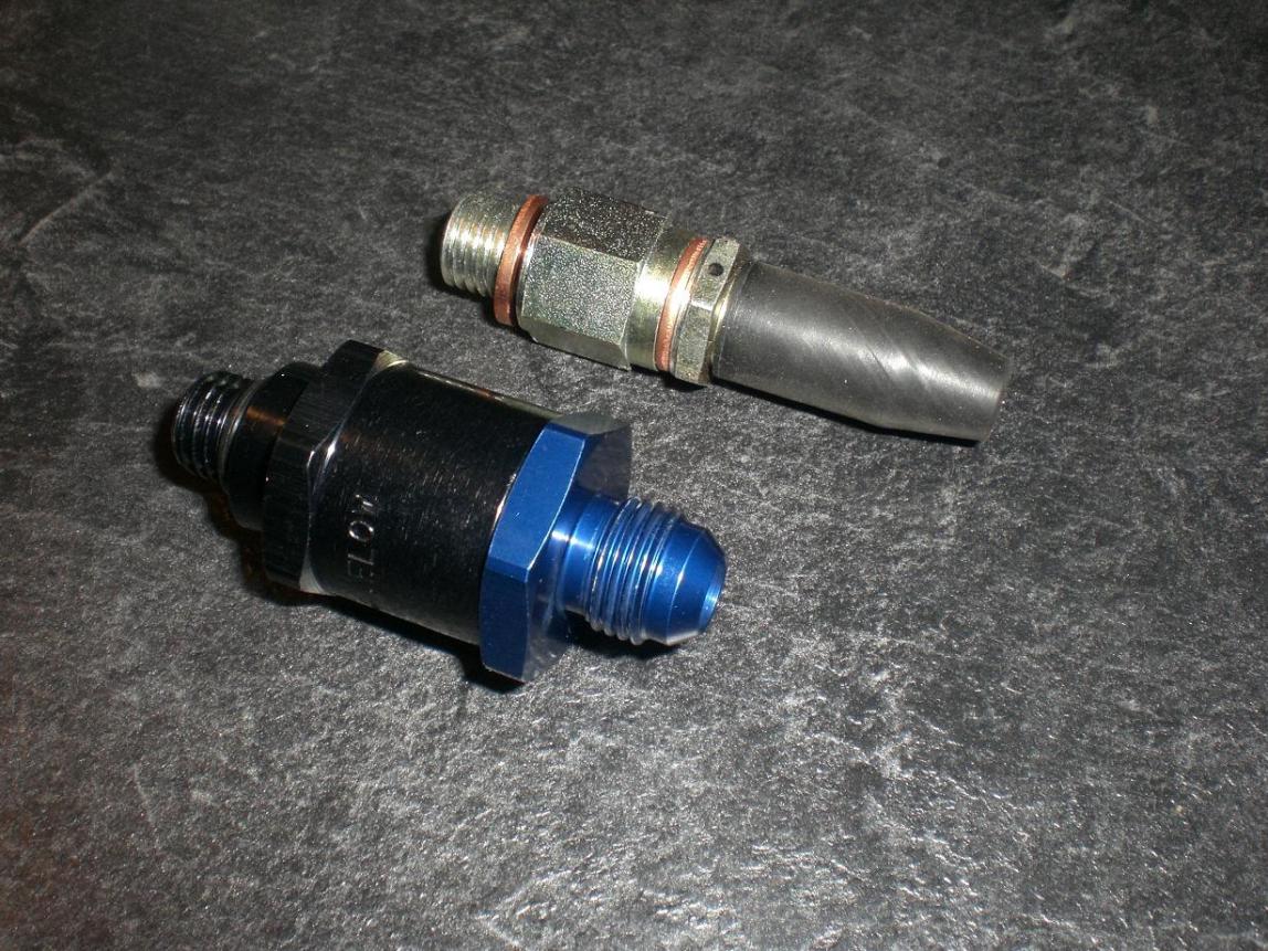
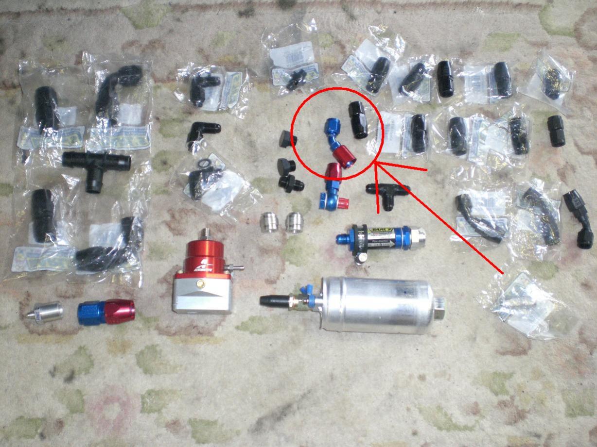
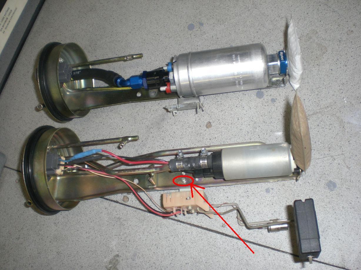
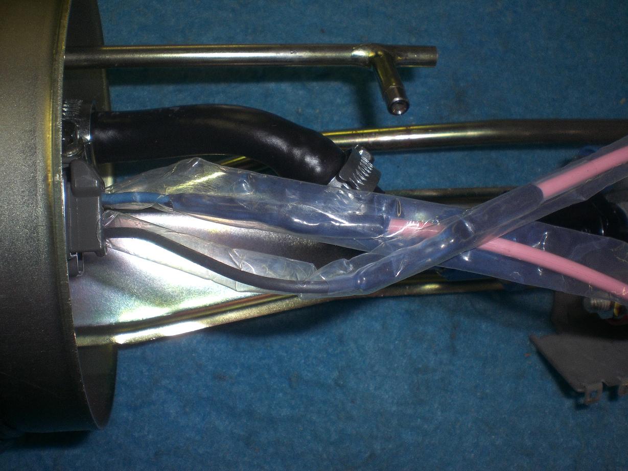
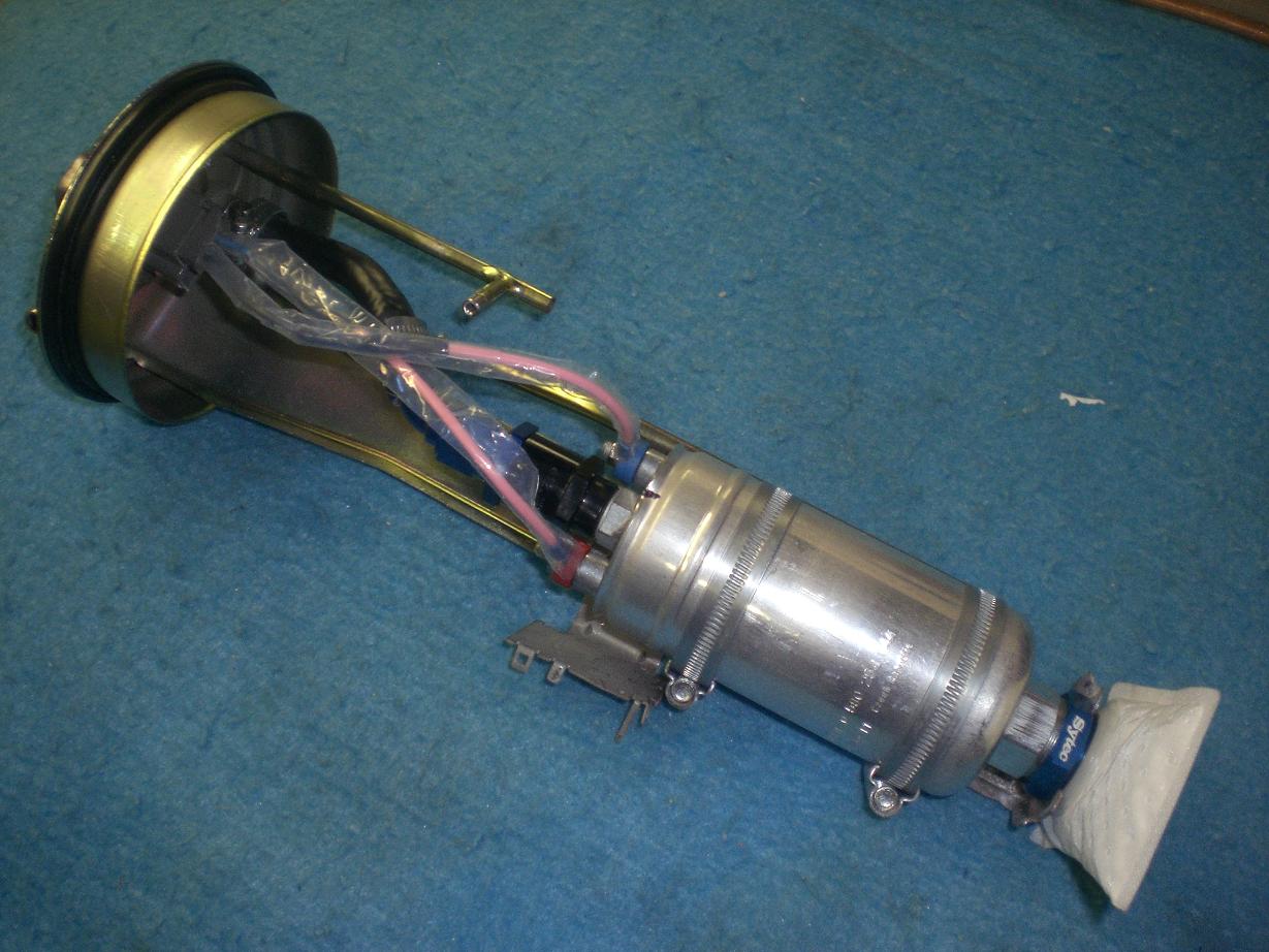
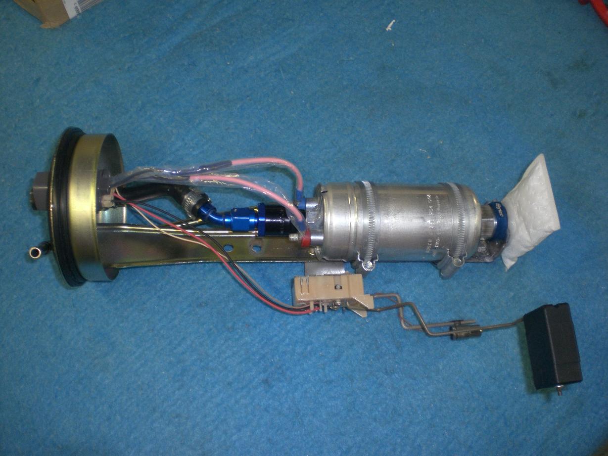
I also finished fitting the Bosch 044 pump. I removed the Bosch one way valve which is designed to be used with a banjo and replaced it with a speedflowstore.com valve. The part number is 612-06 for the dash 6 version and it is available here: http://www.speedflowstore.com/products.asp?CatID=CARBY%20-and-%20FUEL%20SYS The plan was to use this valve with an angled AN fitting with push on hose like this blue and red Earl’s Super Stock one shown here. The part number is 704667 for a dash 6 45degree version. In order to get the pump sitting in a sensible looking position I had to remove the two screws that hold the level sender to the pump hanger. Only one is visible here but this is obvious if you get the parts in your hand. Both screws were shortened by about 3mm allowing the pump body to sit up against the hanger. My Gates submersible hose arrived in time for this so that worked out well. I removed the typical SAE30-J6 piece of hose that I used for mocking things up and replaced it with the real stuff. http://www.gates.com/brochure.cfm?brochure=5091&location_id=541 This is the ONLY hose I could find that is rated for use inside fuel tanks where it is exposed to petrol vapour or liquid; over time, conventional fuel hose will degrade in this environment. I took a close look at the hose on my OEM pump (been on shelf for three years after being in tank for 10 years) and it is just as flexible and smooth as the new Gates hose...it actually seems to be identical to the Gates stuff when you cut it apart and look at it in detail. I compared this to the piece of hose that came with the Walbro 342 pump...the Walbro's hose was brittle and aged by comparison and had only been in the tank for around two years. I have loads of this Gates SAE J30-R10 subversible hose left over as I bought plenty as it was a special delivery item from Belgium and took three weeks to arrive. If anyone needs some then drop me a pm. I played things "safer than safe" with the wiring.... The wire is PTFE (as opposed to something more normal like PVC) insulated which is fine for use in fuel. The connections for this were soldered with hook joints for additional strength and then I made a triple effort on the heatshrink. I also staggered the joints to pretty much eliminate shorting if something happened to the heatshrink. I used a black, fuel friendly adhesive backed heatshrink on each joint. Next I shrunk on a piece of clear PTFE heatshrink over the black heatshrink. The PTFE stuff won't shrink until something like 300+ degrees so you need a good heat gun and have to be careful to avoid melting any non PTFE wire insulation Finally I slipped a long length of clear PTFE sleeve over the entire length of each cable. I have left this "unshrunk". The pump was resting on the bottom part of the hanger (where the stock pump's rubber mount is) but this made the whole thing too long. I ended up chopping the hanger a little shorter but unfortunately I didn't get any pics at the time. I will be removing the pump in approximately two weeks so I will get a few shots then. The upshot of this is that the two large jubilee clips are 100% responsible for holding the pump in place. From memory you'd need clips that will finish at something like 62mm internal diameter for this type of setup. So this is how it looked before it went in the tank (but the lower tand of the hanger was removed as mentioned earlier and the pump sits about 8mm higher).
-
The subtle look I do have a spare #12 forged 90 degree one that'll be in the sale section shortly Here's another pic just for you Jay....