
Digsy
-
Posts
5078 -
Joined
Content Type
Profiles
Forums
Store
Blogs
Events
Downloads
Supra Articles
Gallery
Everything posted by Digsy
-
Do Kolbenschmidt or AE Goetze do forged pistons? I know they do a lot of mass-market cast stuff, but they are pretty advanced companies.
-
I've downloaded the whole MKIV.com manual section (about 700 pictures - fun over a 28800 dial up link), and I'm intending to put them onto a CD sometime with an HTML front end (not to ditract from the hard work someone has gone to in the US doing all the scanning, rather for easier access for my own personal use). Its a low-priority job at the moment, though..! For you guys with broadband, I recommend pointing some kind of site mirroring software at MKIV.com and grabbing the lot. Its an excellent resource, USA spec or not.
-
Probably from the same batch that Lust2Luv had feeding his alarm. Dodgy electrics installs, eh? Tcha!
-
That's when you need Rob's blowtorch wielding friend! Just keep him away from the front of the engine...
-
The diagram seems to show two plugs: One on the engine and one on the rad. Because the J2Z uses an inlet thermostat, would removing the bottom hose only drain the radiator and not the whole system? Hence the need for an engine-side drain too? Alex: My rural dialup connection dropped 80% of the way through sending you the pages from MKIV.com Let me know if you want me to resend.
-
Don't sweat it. I don't work on cars myself anymore (not greasy stuff anyway!) I've e-mailled you the "coolant replacement" page from MKIV.com There's also a detailled description of the whole system in there (runs into about 9 pages). Oh sod it. I'll e-mail you those too!
-
Hi Alex, I just had the coolant changed on my car as part of its service. Checking the invoice, it doesn't say what volume was used, but the cost for the premixed coolant was £11.63+VAT I think you used to be able to buy radiator flushes from places like Halfords or Wilco but I wouldn't like to comment on their suitability for modern engines. As for the odd brown colour (ooh, tempted, tempted) I would have thought that the coolant would have had an anti-corrosion agent in it, but we do have cast-iron blocks after all. Could just be down to ageing. UNless big lumps or sludge fall out I wouldn't worry about corrosion too much. How often? Seems to be every 36000 miles, by the book (reading old threads here, not referring to my handbook so I could be a bit wrong).
-
I thought you were a techie, Mark Front wheel (ew ) cars can suffer from "torque-steer" caused by more torque being transmitted to one wheel than the other due to the fact that front wheelers have one short driveshaft and one long one. The long shaft "winds up" and car pulls to the short side. The more torque you try to put down the worse it gets. Rear wheelers, with the diff in the centre, do not suffer from this.
-
"Nothing to do with massive amounts of torque going throught the back wheels then...? " Not unless you've fitted unequal length driveshafts!
-
I think the noisemaker is set to contact the disk when there is only 1mm or 2mm of "meat" left on the pad. The minimum running thickness is 1mm. My brakes squeal anyway (sometimes)...
-
If you end up with any spare pins from this connector when you have made your repairs, I would be interested in having them.
-
Phil, Yep. Still fannying! I've caused myself lots of bother because of the way I've wired in the stock switch. I won't go into details because its sorted now, but in the end I needed to use two diodes to stop the relay switch earthing out "backwards" through the blown blub lamp, and I also had to locate a wire which was earthed *only* when the lights are on. (Plus I'm only working on it for an hour or two here and there so as not to upset the wife to much). I got all the necessary for the trim panel. UK part is £40+VAT but the blanks for the washer and headlight leveller switches are discontinued. The J-spec part with the single cutout is special order from Japan (ker-ching). In the end I made a front mounting bezel up myself to disguise my "handy" work when I cut the switch into the dash. No idea about the price for a UK dial face, but seems overkill since I'm only going to use the face itself. If I can get hold of a second hand one I will, if not I'll leave it be. Pete, Interesting... What are you planning to print it out onto?
-
Got this sorted now. I've got a wire that grounds via a diode through the "lights on" switch on the stering wheel stalk. Trouble is, because the LHS warning bulb panel is only live when the ignition is on, I have no foglamp warning when the car is parked. Not a big issue but I was wondering if it would fail an MOT on it? Having had the IP right apart now, I am really, really miffed at how close I am to putting a proper legend inside the fuel / temp guage. The bulb location is there, the copper tracks are there, I even have the ground wire running behind the IP that could easily be rerouted. Trouble is, instead of leaving the legend printed on the dial and just not putting a bulb behind it, they have blanked it out completely. If they had left a semi-transparent window I could have printed out an orange legend onto some acetate and slipped it behind the dial face - job done! So because of the shortcomings of the rear bulb fail warning conversion, and because modding the IP is almost possible, and (mainly) because I'm 100% anal retentive, I am now back on adding the fog lamp legend to the dial face, but I'm at a loss as to how it might be done. Options I've considered so far: 1) Print out a complete new dial face myself (too much hassle). 2) Punch a hole in the existing dial face, just to let the light through (bit of a bodge). 3) Cut out the blanked section of the dial face and glue in a new section with the legend (disaster if it goes wrong, and a bit of a bodge too). Actually, if anyone has fitted a white dial set an has a J-spec (or even better, UK spec) dial face kicking about, I would love to have one to experiment on. I think I'll post a thread in "For Sale / Wanted"...
-
By way of background info (very brief because this has been covered loads of times before - the search function will probably return a Lord of the Rings sized tome of information): The most common way that an importer (including JIC) uses to delimit a car is, as Matt says, by raising the limit to 180mph by feeding the ECU with the same divided signal as goes to the speedo. On the Supra this is especially easy because the ECU gets its speed signal from the odometer. However, because the whole car now thinks it is ging at 5/8 of its true speed, this affects all the other speed-related systems: PAS, cruise, active spoiler, and on auto cars - the gearbox. See the TRL website for more information. Additionally, if you could get to 180mph the limiter would cut in again (not a huge problem for most of us). For this reason I specifically asked JIC to only convert my speedo to read in MPH. This in isolation does not affect anything else. At the time the only alternative was the HKS system (£150 approx) and I didn't want to spend that sort of money for the time I spend driving at 180kmh plus! The accepted "proper" way to delimit the car is to use a gizmo that allows the speed signal to enter the ECU unaltered until just before the limiting threshold, at which point it is "clamped". For example, the ECU sees the true speed up until, say, 179kmh and then no matter how fast the car goes the ECU continues to see 179kmh. Thus the inbuilt limiter *never* cuts in. HKS use this approach in their SLD (plus some other gubbins that talks to the auto box, and seems to modify the shift strategy). Pete Betts makes a unit that delimits in the same way but costs about half as much (plus the instructions presumably come in English!)
-
No, that makes sense because when I interrogated them the JIC guy said they just connected the divided signal to the ECU via the odometer (with all the associated side effects that don't need repeating here). Hence my asking them to convert the speedo only. If the grey wire was a "proper" delimiting signal it would have made more sense for them to use that instead.
-
Marnin' I had my dash apart again yesterday (getting really good at it now) and had a closer look at my KMH/MPH converter box, as fitted by JIC. Its a unit made by FES (assuming that is the company name) and the model number is CK-DV-99 It has red and black wires for +12V and earth, and a yellow wire for the divided signal to the speedo / odo (only connected to the speedo on my car, as requested). Thing is, it also has a grey wire which is labelled "ECU", which is not connected. Now, I've not heard of FES. Is this grey wire just another divided signal (identical to the speedo one), or is it a proper SLD "capped" signal that I could feed to the ECU to delimit the car much like the HKS or TRL equivalents? Bear in mind that I have an auto. I think Paul Booth's investigations showed that the HKS unit's connections to the auto box had nothing to do with the delimiting, rather a remapping of the auto shift strategy to make the most of the higher to speed. I've tried a websearch with no luck. Comments from techies welcome! (edited to correct names - doh!)
-
And mounting that beaker of pure melting ice for the cold junction in the engine bay it is going to be a pain. Sorry. Not being helpful now. Martin, most of the temp sensors I have seen have a tapered thread which screws into a rigid part of the intake system, usually upstream of the throttle body. I have seen some in plastic systems that have a bayonet style attachment. I'm going to stick my neck out and say that the ones I've seen are thermistors...
-
This was all I could find on the net about Cooper's rings. There's a jeweller's called Coopers with a heavy web presence that kind of muddies the search engine results a bit! Cooper's rings - Jus' like that! Glass, bottle, bottle, glass.
-
What is the temperature sensing element? Thermocouple, platinum resistance, or thermistor (or other)? Seems odd that Alex's unit is looking for a voltage / temp relationship that works in the opposite sense to the one that his air temp sensor is putting out... Thermocouple - creates voltage proportional to temperature. Platimun resistance - resistance increases proportionally with temp. Thermistor - resistance decreases proportionally with temp. If the output voltage is dropping relative to earth, could you measure it relative to a 12V source without blowing anything up? *Disclaimer. Please don't try that until someone has confirmed it. I don't even know what an SBC-id is!
-
Lag is pretty much all to do with turbo impeller inertia. When you are on boost you can force the air through all sorts of weird and wonderful shapes with relatively impact on performance, compared to the sort of intake pipework you need to use on an NA engine. I think the volume of air in the pipes would make a difference is there was an appreciable pressure drop across the intercooler. Otherwise I think more free flowing pipework with a larger diameter (and hence a greater pre-manifold volume) would be preferable. I did read some of the GTR thread about IC mounting. Maybe I'm being over simplistic but I always thought the main reason for mounting radiators / ICs at an angle was jst so you could fit a bigger one in a given frontal area.
-
I think the things that Adam is talking are called "Cooper's rings". Pretty much like he says, but they have a hollow section. Could be wrong. You might be able to do it with wire too. Intrigueing...
-
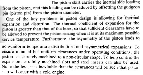
Here's the last piece of the puzzle, which was sitting in a book over my shoulder the whole time (Introduction to Internal Combustion Engines - Richard Stone).
-
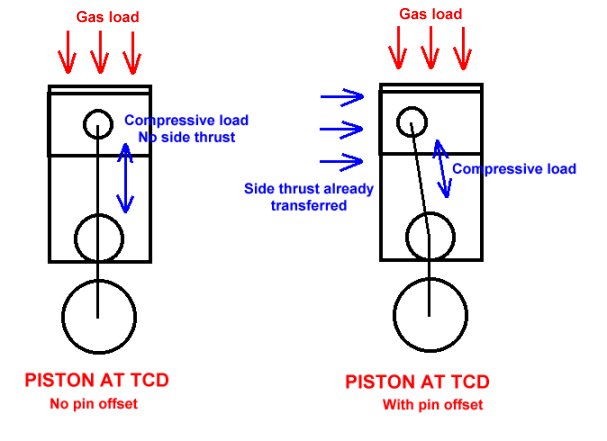
And these sketches are my attempt to show how piston pin offset transfers the side thrust to the cylinder wall before the piston reaches TCD. Hopefully on Monday I'll be able to tie all this together with a proper explanation!
-
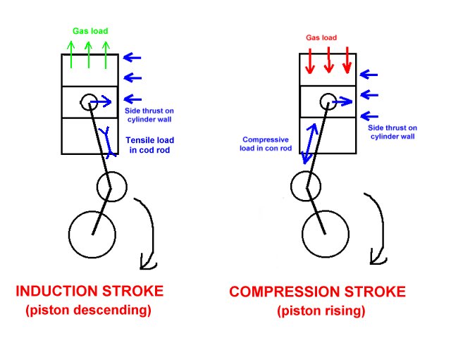
...and here it is for the induction and compression strokes. Spot the deliberate mistake. I've reversed the symobols for the compressive and tensile loads in the connecting rod. DOH! Never mind...
-
Since there was a bit of interest generated over piston slap in Dil's the cambelt change thread, here is a new one in which we can further investigate the phenomenon. I've attached a quick sketch showing how the piston side load reverses during the power and exhaust strokes on a four-stroke engine. I'm pretty sure that piston slap has something to do with this, coupled with - as Myles said - the piston not fitting the bore properly intil it has expanded slightly.


