
Digsy
-
Posts
5078 -
Joined
Content Type
Profiles
Forums
Store
Blogs
Events
Downloads
Supra Articles
Gallery
Everything posted by Digsy
-
Over reading. Sorry. Your speedo will be over reading because your rolling radius is smaller.
-
Not much. You'll have a tad less tyre roll around corners because of the smaller sidewall. Your speedo will be under reading by about 4%, and if you are hyper-sensitive to these things you may notice a tiny, tiny bit less acceleration when you change to 50's.
-
Welcome aboard. Standard 16" tyre sizes are 225x50x16 front and 245x50x16 rear. Check it out.
-
When we talk about removing the converter, its probably worth checking that all the severed connections are remade. Since there's no speed signal, the re-broadcast wire from the odo may have been cut at some point, and this may not necessarily be near the odo / speedo.
-
Welcome to the club (I'm always careful to welcome SZ owners ) Yes, have a poke about. Speedo conversion is one of the most frequently talked about topics here. There are loads of ways to do it, but only a few ways to do it right. I would bet that there is nothing that can't be fixed by a little detective work and a few hours with a soldering iron. Your garage isn't looking beyond the end of its nose.
-
I was working on the assumption that at the moment he has no 5/8 divider in the circuit. If he keeps the same dial face and puts a divider in, then yes the speedo will under-read.
-
if I'm reading this right then what you have is the simplest (and nastiest) type of km/h to mph speedo conversions: A completely new dial face that is calibrated in MPH. The J-spec speedo face goes up to 180km/h (112mph), and the needle goes all the way around. Instead of changing the signal that goes into the speedo so that the dial reads off mph on the existing face, your importer has changed the whole face. If you delimit your car, your needle will literally go off the scale. What you need is a combined speed delimiter / speedo converter from Mr. Betts (who I'm sure will make an appearance shortly). This will delimit the car AND convert the speedo input signal to read off MPH on a J-spec KPH dial face. If you have a look under your 120MPH dial face you may be lucky and find the original J-spec face under it. If not, you will need a new J-spec dial face that reads up to 180km/h. All that you need to do then is fit that, and put an MPH sticker over the KPH legend. HTH.
-
 Here's the lockup clutch in the MKIV auto box. Make sure you have one of those metric adjustable spanners to get it off
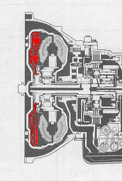
-
You could sell it as an "unfinished project"... ...you don't have to mention that you haven't gone any further than working out the bore sizes!
-
Stock bore / stroke is 86mm square (0.4996 litres, give or take ) 87.5 bore would give you just over 3.1 litres.
-
I only have one pretty lousy picture of the block, but it looks quite meaty around the cylinders. I don't think there's any coolant between them in the siamesed walls, either (apart from what looks like two drillings, but the coolant flow diagram on MKIV.com doesn't show any between-cylinder flow). An extra 2mm on bore would give you 3.14litres. I think 3.2litres would be pushing it. You might need a new head gasket, depending on how close the sealing bead was to the cylinder bore. (Not as special as my cam profile post - my wrists are still aching from that one. At least I think that's what it is Chris is right, without a block to dissect, or a drawing, boring out would be a brave move!)
-
Most of what I've put above draws heavily from "Introduction to Internal Combustion Engines - 2nd edition" by Richard Stone, and published by the SAE (Socienty of Autmotive Engineers). ISBN 1-56091-390-8
-
I suppose I'd better have a stab at this I'm not too sure whether you can put a cam's characteristics just down to its profile alone. How the engine performs will be down to the profile of both cams, and their timing. Typically, you want as much air in the cylinder as possible on any engine, let alone a sporty one. Assuming that the valve diameter remains constant, the only way to do this is to either make it open further (increased lift) or make it open longer (increased duration). If we make another assumption: that we won't change the valve springs, then the maximum valve acceleration is also fixed. You can still just make the valve open longer by having the same opening and closing ramps and a more blunt profile, but if you want more lift then you are also forced into making the duration longer so that the lift takes place over a longer timespan. The choice of increased lift or duration (or both) will depend on how well your valve flows air at a given lift. If we imagine for a second that you could freely increase the valve lift you would find that beyond a certain point it ceases to make much of a difference to the overall flow. This is a mathematical function of the lift and the diameter of the valve. So if increased lift has a top limit which is governed by the valve diameter (which we've assume we want to keep fixed) then the only way to get more air into the engine is to increase the duration. So why not have as wide a profile as possible and be done with it? Well you could, but there's all sorts of ther things to take into account like the other valve, the motion of the piston, the valve dynamics, intake and exhaust pipe tuning, and (in a production engine) stuff like fuel economy and emissions. For one thing a long cam duration means lots of valve overlap (when both intake and exhaust cams are open at once). This is good for "blow down" - evacuating all the inert exhaust gases from the cylinder by chasing them out with a fresh intake charge. This happens at the end of the exhaust stroke, which is also the start of the induction stroke. The piston is at TDC here, and the exhaust valve is being held open for blow down and the intake valve is starting to admit the fresh charge. Since there is a mechanical link between the valves and the pistons, the extent to which you can do this effectively is limited by the minimum clearance between valve and piston: i.e you can't hold the exhaust valve open very much while the piston passes TDC (you can with valve pockets but these have their own foibles and I'm going to ignore them). Additionally, in an NA engine blow down only really works at WOT. Before WOT the low intake manifold pressure may cause the exhaust gas to be sucked backwards, causing poor performance at part throttle and idle (which is why race engines don't idle worth a damn - and you thought all that throttle blipping was for show! ) The other penalty is that when both valves are open at WOT, some unburnt fuel will pass right through and out into the exhaust, which is bad for fuel economy. In an NA engine all of this will be interacting with pressure pulses in the intake and exhaust pipes which as Chris says will create "sweet spots" in the torque curve. Finally, something which I don't really understand is that by precise timing of the valve events you can reduce the "pumping losses" - the dead work that the engine has to do to get the air into and the exhaust out of the engine. You might be able to get more torque by opening up wide and then slamming the intake valve shut at BDC, but it can be shown that early trapping of the intake charge does not have as much effect on overall efficiency as other factors, plus it will decrease the overall valve open time (hence limit the airflow) plus it will be beyond the capability of the valve spring. In actual fact, late intake valve closing can just as beneficial for the reasons stated above. This pretty much explains why variable valve timing (VVT) has caught on in such a big way. Typically, you have a fixed "cooking" profile, but retard it for minimal overlap and late inlet valve closing (pumping losses - don't ask) at low speed / load (and coincidentally during the emissions cycles), but at a certain speed / load point you advance it. You dont get any more flow, but maybe the intake tuning works better with that particular timing above that speed, plus you get more overlap. First generation cam timing "phasers" were two position with nothing in between, so instead of a single big compromise on valve timing you now have two compromises to choose between depending on what the engine is doing. The current generation of phasers are infinitley variable with engine speed. Honda take a different approach with their VTEC system, which has two completely different cam profiles to choose between - a "cooking" profile for pootling around town and effectively a race profile with a longer duration and higher lift for WOT stuff. Even this technology is reaching its limits, which is why so much effort is going into electro-mechanical valvetrains. Once freed from the confines of a direct mechanical link between crank and valve (however "variable" phasers and VTEC attempt to make it) the door is open to maximum valve opening, and infinitely variable profiles and timings. You may have noticed that a lot of this applies to NA engines. I would have thought that life on a turbo was much simpler because the sensitivty to intake and exhaust tuning was removed when on boost (part throttle and idle performance would need to be retained in the stock engine setup though). Not really sure if I've answered Alex's question or just blathered on for while, and it didn't all come out of my head. I have a reference book right here I agree that a deep meaningful discussion about it here will be very difficult (I've just paraphrased virtually a whole chapter from one book plus a chunk of what I can remember from another). HTH anyway!
-
Alex, By a galactic coincidence I was going to post a thread today asking for MOT garage recommendations in the Norwich area. Please could you PM me the place where you took yours? Cheers,
-
Nothing aganst the stock pulley at all (I seem to have been posting a lot about it recently, though). A few people have posted stuff about it recently. I wondered whether you had read one of my other posts when you said you were going to keep the pulley because of its damper function, but then you said you were having the cranktrain lightened so I wondered if you knew that this would affect the pulley. Now I know that your cranktain mods are minor, and limited to removing sharp edges, so it probably wont make much difference to the TVD. Terry Saunders says there is no prob with running without the stock TVD altogther on the stock crank. A special TVD would be sh*tloads, and I don't think any of the mainstream companies would be interested. It would probably be simpler to go for a gorilla-strength billet crank and forego the TVD altogether if it got to the point where anyone thought it would be a concern.
-
No arguments on the theory of rounding. All sound stuff. I was wondering where you were going to do it? If you are going to do it all over, then I guess you've answered my question. The most highly stressed parst of a crank are the fillets and oil holes, however. You can shot-peen the fillets and there is also a process called "ballizing" (no sniggering at the back!) which does the same for the oil hole breakouts. A spherical tool is pressed under high pressure into the open end of the oil hole to do the same job as shot peening, but without damaging the bearing surface. As for the front crank pulley / TVD, I have no doubt that you can balance the whole assembly as a purely rotating mass, but if you alter the masses of the component parts of the cranktrain, then the rubber damper and inertia mass of the pulley will be out of tune with the vibrations in the cranktrain, with unpredictable results. Nice to hear of a complete teardown job!
-
Just a few comments: MKIV.com does say that the rods are forged. It does not mention if the pistons or crank are, but apparently there is some evidence from the US that says the crank is. I would be interested in seeing some details of the crank "rounding" you describe, and also the similar treatment that your block is going to get. If you are going to have your crank lightened, you may as well bin the front pulley anway, as you will change the cranktrain tuning so the stock TVD will be useless. I think you are the first person I've seen on here to mention fitting upgraded bearing shells (apologies to anyone else if not).
-
Clutch release bearing, or input shaft bearing?
-
Couldn't possibly hold anything aganist your post. Not with that many smileys!
-
Depends how much the material around the holes flexes. Last time I cleaned my car I noticed that the "Chipsaway" repair job on my front bumper moulding has started to crack. Probably because of the flexure in that plastic part. That was a 1" diameter hole backed with metal mesh attached with cyanoacrylate (superglue), filled with a plastic weld material, with body filler over the top. The filler has cracked away from the bumper around half of the circumference of the hole. Looks like he'll be coming back to re-do it under warranty! I used a lot of body filler in metal areas on my first car (Metro) and none of it ever cracked.
-
I just read the but about the underdrive pulley in "for Sale." The stock crank pulley is heavy because its also a damper which stops the crank twisting. No side affects at all from removing it?? Sorry. I'm having a reliability-on today. It'll pass, hopefully.
-
Just thinking aloud, there's absolutely no way you can compare how reliable these highly tuned engines are, anyway. One guy might have a 700hp lump on stock internals, but he might be happy because he only takes it up that high every other month, and it hasn't blown up yet. On the other hand someone may only have 550hp with a completely strenghtened base engine, and can happily race it every day. Either guy could also do a complete stripdown and rebuild after each meet, too. Both would probably claim that they had a reliable car.
-
Well GM have made a 1000bhp drag racing engine out of a 2.2 litre L850 lump such as you might find in a current model year Saturn, SAAB, or Vauxhall / Opel product. Its only got to last for a few runs, but - hey - they did it! Over 100% increase in specific power output is one helluva lot for any engine - even one with a cast iron bottom end. Making the huge assumption that the Max Power engine is durable, I would take the words "based on" with a huge pinch of salt. At that kind of output, either a lot has been beefed up, or something, somewhere is breaking... IMHO of course
-
EGR is there purely for emissions reasons. Many people think that its to reduce HC emissions by recycling unburnt hydrocarbons through the engine again. Logical though this is, its not correct. It is there to control the speed of the combustion process by adding a tiny proportion of exhaust gas - which to all intents and purposes contains no combustible material - to slow down the burn. Fast burn = NOx (oxides of nitrogen). Slow burn = unburnt hyrdocarbons. EGR allows you to get a trade off between the two. Because its an emissions thing, its only "on" in the part of the speed / load map where emissions are actually measured: usually below about 3500RPM and low load (up to about 33% of WOT). It will differ from engine to engine. The amount of exhaust gas added is very small (its usually taken from just one exhaust runner and sent to all the intake ports). I suppose it would raise your charge temps a bit, but in that part of the speed / load map I doubt that would matter. And there endeth my knowledge on the subject!
-
I'm fannying about with my petrol gauge dial face (changing one of the logos in there). Someone (possibly Phil Irwin) said you can lever the needles off with two teaspoons, one on each side. Anyone who has fitted a white dial or lumi-dial kit will know how to do this properly. I rekon by tomorrow we'll have an answer one way or the other.

