jagman
-
Posts
1555 -
Joined
-
Days Won
18
Content Type
Profiles
Forums
Store
Blogs
Events
Downloads
Supra Articles
Gallery
Everything posted by jagman
-
Was Pretty much what I did - except I added marvel mystery oil to the spark plug holes and left for with a few days before pumping out . And when coolant was empty - I flushed the heater core . I had no issues with . anything .cleaned all the coil packs with them out . Fired right up smooth as .
-
 The lock up of the torque converter operates similar to the gear shift - there is a small clutch that is solenoid operated on /off - the Ecu calculates when it locks …..again a speed signal is used ,along with throttle position and the brake pedal switch (unlocks/locks with brake pressed ) once calculated if in lock or not it operates the solenoid …..it’s again a simple error calc to put up the fault code ie Ecu sends voltage and expects to see a drop in its internal resistor …open or short circuit - what it can’t do is work out if it’s calc is wrong ie a speed signal error or internal capacitor leak - it’s not that smart ! The speed signal is derived from the gearbox sensors (later cars used wheel speeds as well ) and speed is used on other cars like soarer for door locks ,suspension ,shift ,OD and steering - ALL can go wrong if the converter is wrong ! - you can measure the resistance of all the solenoids from the Ecu connector pins -so a quick easy check of wiring - but in the first instance a new converter may fix all issues inc trac
 -
The pink wire soldered is the speed signal wire : speed is used in various areas - it’s used to display the speedo ,and also used by the Ecu for speed limiting ,also used by Ecu for gear shift speeds . Often the speed signal is converted from km to miles - this removes or actually lifts the limiter . A chip is soldered in - behind the speedo or near the Ecu - it has an earth ,a power , and an “in” and “out” wire . These chips very often fail and the speed signal gets corrupted - with various issues . The ECU is used to send commands to the gearbox to shift and go in /out of OD -speed signal is used to calculate when and the ECU supplies a 12v to the gearbox solenoid - the solenoids in the gearbox can fail and do fail . The Ecu supplies 12 v via an internal resistor and the solenoids are earthed internally in the box . If 12v is supplied to say solenoid no 2 - the internal resistance has a voltage drop across it as current flows - the Ecu measures this volts drop …that’s how it decides if there is a fault - the voltage drop is not in limits - it could be too high or too low - it can’t tell ….hence the open or short diagnosis and commonnessnnn fault code . Hence ECU internal fails a possibility - you can swap the Ecu to eliminate , you can swap the speed converter unit ,you can measure the current flow and voltage to the solenoid and listeners to it - a positive click and compare between solenoids . The trac also uses the same speed signal . I would start with the converter ,they are real cheap electronics used in them but
-
Is there a list of all the plugs found on the MK4?
jagman replied to SUPRA4EVA's topic in mkiv Technical
https://www.switchelectronics.co.uk/products/5-way-straight-pcb-crimp-housing-2-54mm?currency=GBP&variant=45606348554549&utm_source=google&utm_medium=cpc&utm_campaign=Google Shopping&stkn=bbf1d20e1ed7&gad_source=1&gbraid=0AAAAAqEgT0Abwtc4Pn-nx2eEQMtjf6S9v&gclid=EAIaIQobChMIutGUn6bIiwMVK5JQBh3O5ydpEAQYBSABEgJRfPD_BwE the mirror has a 5 pin connector - male pins ,by convention all connectors that have power are female , and all connectors that are powered are male …this is to prevent short circuits by 2 male pins touching .the stock connectors have slots - orientation to stop cross connections to a wrong plug . The pin spacing is 2.54 mm between pins . The molex has the correct spacing but no orientation - it should just push in . I am not sure what your issue is - a damaged connector ? Pins are also available a few hundred female pins for maybe a pound , these can be fitted with pliers /side cutters so no crimping tool needed …correct tool is over £300 . You can also just replace both connectors - extend the looms to for ease of fitment . I don’t know what your issue is the ganador mirrors dont come with OEM connector - they have a circuit board with the 5 pins on top - all open ,but they do connect to OEM door loom connector - much like molex connector - -
Some complex stuff going on here , as you are pushing stress levels on the engine …I think CHT is an important parameter ….I am from an aircraft background and CHT is the main monitoring parameter EGT is fine but looking at heat energy leaving via exhaust valves at a relatively low load situation rather than the higher in cylinder loads at peak . Cheap and easy to install and will give in cylinder data ,that also links to oil temp control and water temp control (new rad fans)and handy for any nitrous use . I guess that the gearbox clutches are the main torque limiters ,any stronger ones available?
-
You use the 12v wire that supplies the FP Ecu- shown as blue in diagram - this is ignition switched live . Ie ignition on - relay operates and pump runs . The relay can now be a heavier duty relay and use heavier duty wire from battery to pump - fuse - 87-30-pump . The ECU is unplugged and does nothing . As stock the ECU puts out either 9v or 12v on the fuel pump line (brown) if you use this the new relay can drop out if at 9 volts (it’s a 12 v relay) - the inputs to the ECU were to show if the engine was running and stop fuel pump in an accident and to delay the fuel pump switching off with engine switched off - to prime the fuel lines for next start . And to drop the output to 9v at low power - this reduces the pump flow at idle to reduce the pump return to tank flow rate and reduce tank heating - at idle the majority of fuel is returning to tank and heated as its pressurised to a higher temp and picks up engine heat as it flows - effectively reducing the octane level when heated . These are the functions you lose when bypassing the ECU - you keep some of them if you use a 9v operating relay and wire as shown in diagram (lose the tank heating part ) The 9 volt switching is nothing to do with pump life as usually quoted and all about fuel heating - using a bigger flow pump adds to the return fuel temp - problem ? Not really unless you are sat for hours in traffic and then spank it at full power and high boost while losing some octane with temp
-
Is there a list of all the plugs found on the MK4?
jagman replied to SUPRA4EVA's topic in mkiv Technical
Molex 2.54 pin pitch connector -
Is there a list of all the plugs found on the MK4?
jagman replied to SUPRA4EVA's topic in mkiv Technical
90980-11182 is the OE 5 pin connector but not all pins used on some cars ( depends if folding or not ) I use a molex connector - you can get a box of connectors and pins - 2/4/5/6/8/10 pins male and female with about 200 pins and sockets for about £15 , so plenty of spares for future use - pins are also fitted with a pair of pliers ,no crimp tools needed -I add the smallest tad of solder . These also fit the ganador pins connector -
They just don’t focus light in projector lens set ups or light assemblies not designed for led . The LS 600 has LED headlights and they are great - but they are motorised in an array and each headlight cost £5000 . in fog lights they cause more vision problems than they improve !
-
The viscous clutch fan system is the rolls Royce of fan cooling - water cooling the engine is done to regulate the head temp to a constant temp - no matter what load is applied - regulators - 1 the thermostat 2 the water pump - faster the engine the more flow 3 the fan - viscous fan alters with ambient temp regulating for hot or cold days - it also regulates for engine speed faster the engine the faster the fan - a superb regulator ! aluminium (heads ) do not like varying temps it creates stresses and constant temps give constant clearances . elect fans do not regulate for ambient air temp or engine speeds only for water temp variations - they also cycle on off which has a hysteresis and causes temp cycling - the complete opposite of the requirement . It is the budget option and will never get close to a viscous system which will outflow any electrical fans !!! that’s the tech answer - the only reason elec fans exist is that transverse engines have to have them and they are cheaper to manufacture and design . : cheap front engine transverse cars not for one of the best engines ever made !
-
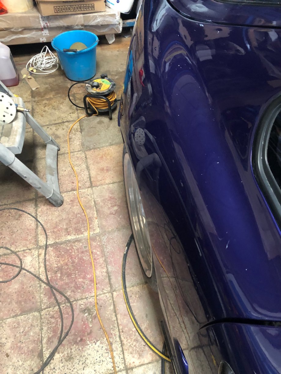
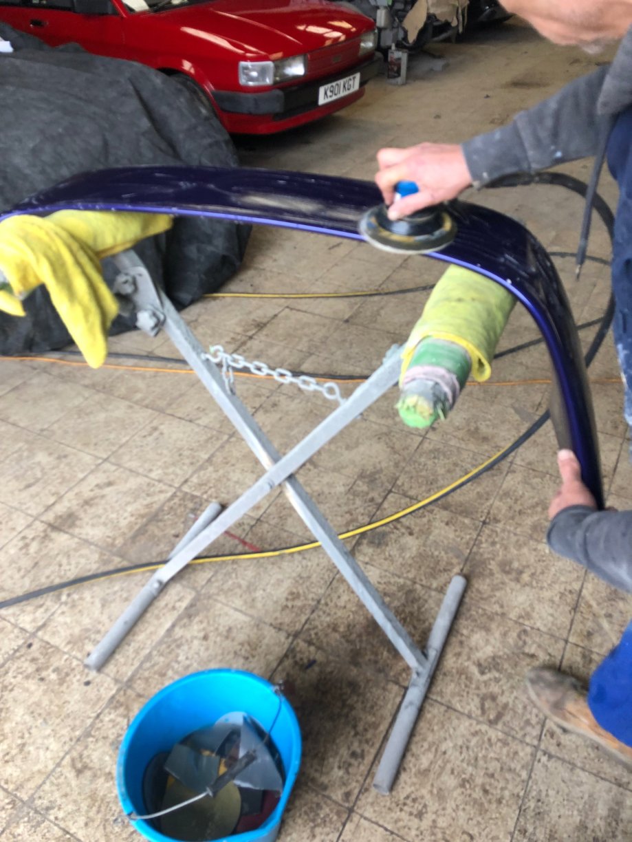
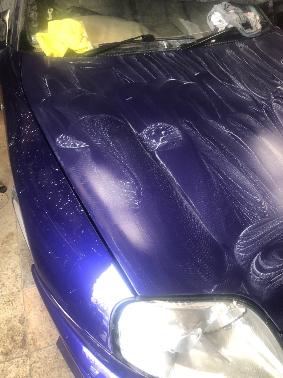
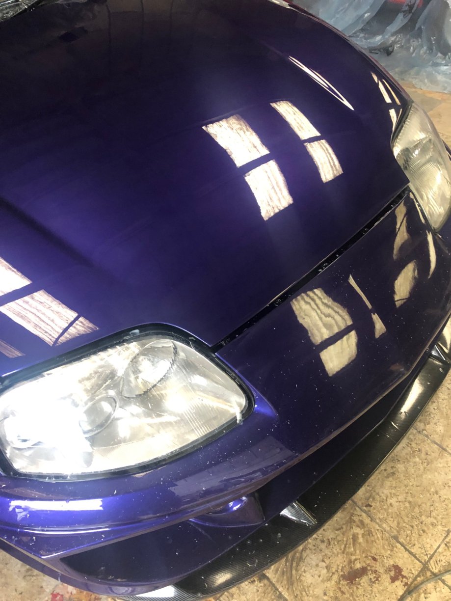
Paint …… when factory paints cars they use an automatic spray system - this uses electrostatic charged clearcoat - it is very thin and saves material cost . All clearcoats have an element of unevenness and during drying have orange peel . Manufactures grade this ,cheap cars =more orange peel . High end cars wet sand . repainting cars always have a thicker clearcoat applied -due spray gun pressure . Once dry clearcoat can also have dust ,hairs , and pin holes . so it’s wet sanded and inspected by eye , every square inch of it . the first sand show any high spots or the worse areas of peel or pinholes , moving light source to check all angles . You work your way down the grades of pads in 4 stages - 2000 down to 8000 grit - the early stages you see the clearcoat coming off as a creamy white colour . You can also feel the finish with your fingers and you use fresh towels from a sealed bag - so spotless clean - any dust will cause a swirl . Then another 4 stages of cutting and polishing using different grade compounds - any pinholes need touching in with clear and repeat the process . best left to someone who has years doing this !! Only once all completed can you apply the wax coat ,first the hydroscopic coat -only one coat ,then apply the finish wax coats - these you can layer up - hence the large number of hours needed A pic of the rear side panels , the rear is about 2 inches wider than stock - but you can barely tell - you would have to put it side by side with a stock car to see it which is exactly as I wanted it - a wide body that doesn’t look wide body - does that make sense ? At least another week of paint polishing left - over 80 hours total !!!!!! there is no such thing as a quick respray ,dark cars show everything!!!!!
-
Once you leave a car off the road , you tend to make it into a mountain of a job rather than a small hill - the longer you leave it the worse it seems . BUT the reality is that is is not as bad as you imagine ! In my case I have made it way more complex : over the years things have moved on ….”small” turbos now make big horsepower and boost at crazy turbo speeds . 8 speed gearboxes !!! Active AI speed controlled suspension! we all know the base engine is a fantastic design - 3x factory power ratings increase is possible and done often - part of what I’m trying out is to get some data : what happens if you add a second intercooler (chargecooler ) , at what point does the head hit temp issues , what is the effect of fuel cooling . Water meth injection to the intake ports what effect and what limits . Can you improve head water flow and how does this affect head stress /temp . can you increase power without oil temp increases , how far can you push pump fuel octane … there is always a mechanical limit engine bottom end and such - hence the engine was rebuilt with rods /bolts/bearing /pistons and so on and is all new to allow me to push it a bit and not run into wear items like piston rings worn or such so I have taken 3 months off work to put it all together and see what happens …….. once you start it’s far easier than the mountain you thought you had to climb …step by step . Starter ,alternator ,blowers ,windows wipers steering ,and most everything else still worked as if it was parked yesterday ! In your head they could all be knackered but NO ,probably all better than if you had driven it for 10 years ,not one stuck relay -the only thing so far was one brake light bulb holder corroded !
-
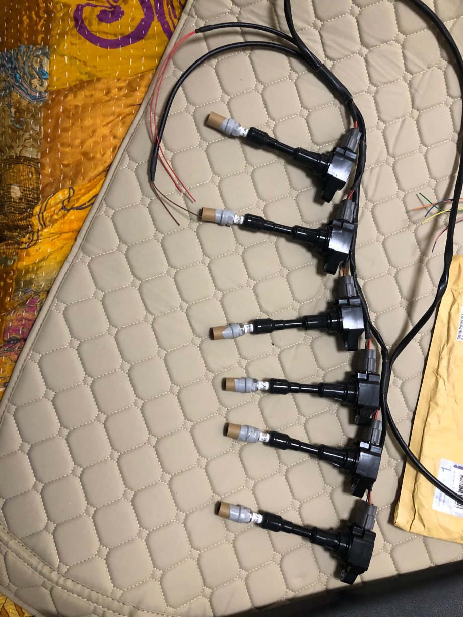
Some bits arrived r35 coil packs ,and more bits on order - fuel cooler ,using a water /fuel heat exchanger and the chargecooler water circuit to cool , manual clutch pedal assy , and brake pedal , Haltech linear position sensor and a clutch emulator - to manual shift the zf . Started the paint compound correction this will take about 30 hours flatting and polishing panel by panel and then some fusso soft 99 hydrophobic coat and a final fusso mirror shine coat - it’s a lot of effort involved ! Going for a top show quality finish and it takes time and effort !!
-
I paid £1500 for the box , it was sent - to a race gearbox specialist who rebuilt it and replaced the Kevlar clutch packs with stronger packs as a one off - I imported the billet sprags from the US - Titan I think -£600 and they were fitted - £2500 for the build and conversion . high stall was around £400 . I have no idea what a similar spec would be now - don’t think billet sprags are available anymore - £1000 would be a cheap price I guess as its No use to me and should not be sat on a garage floor for years . It was rated for 1500 hp - so really for high power spec cars - there were some other internals done but I don’t remember exactly what now . Done less than 500 miles
-
Some new plugs arrived today ,so fitted them and when for the start ………..fired up instantly and ran smooth as you could wish for … I was well pleased ,ran it for 30 mins and topped up the coolant and bled it , heater super hot . One small oil leak on an oil cooler union , tightened and ok ,and a small leak on the fuel pump banjo ,again nipped it up and fine . alternator and power steering all fine . So good progress and mostly wiring and lights to sort ,but about 4 weeks and should be all done ,ready for the ZF box and new turbo and injectors . Anyone want an updated boostlogic box with billet sprags and hi stall converter ,good for high power cars -let me know , I don’t know of any other in the U.K. with the updated sprag and updated Kevlar clutch packs
-
they do polish up alright by hand .
-
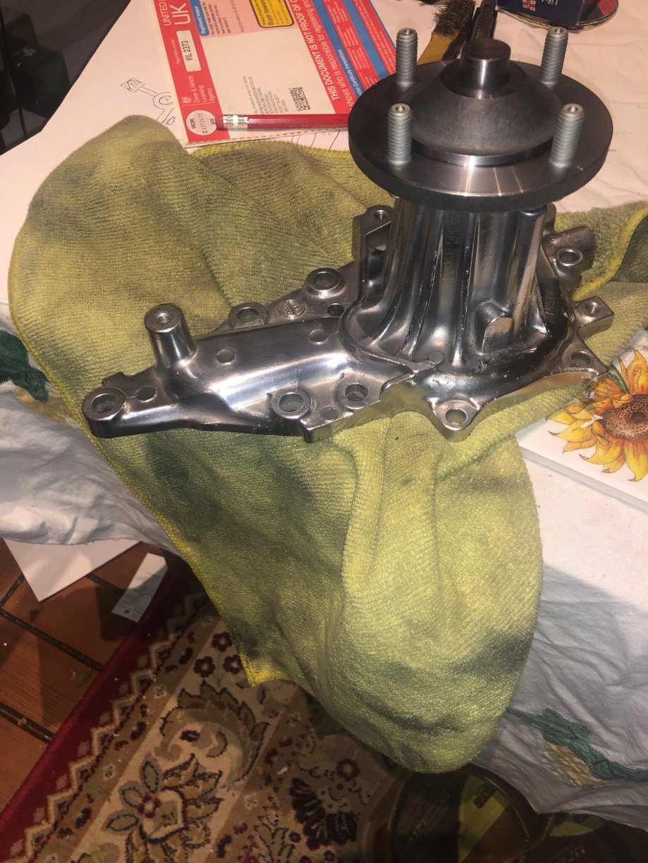
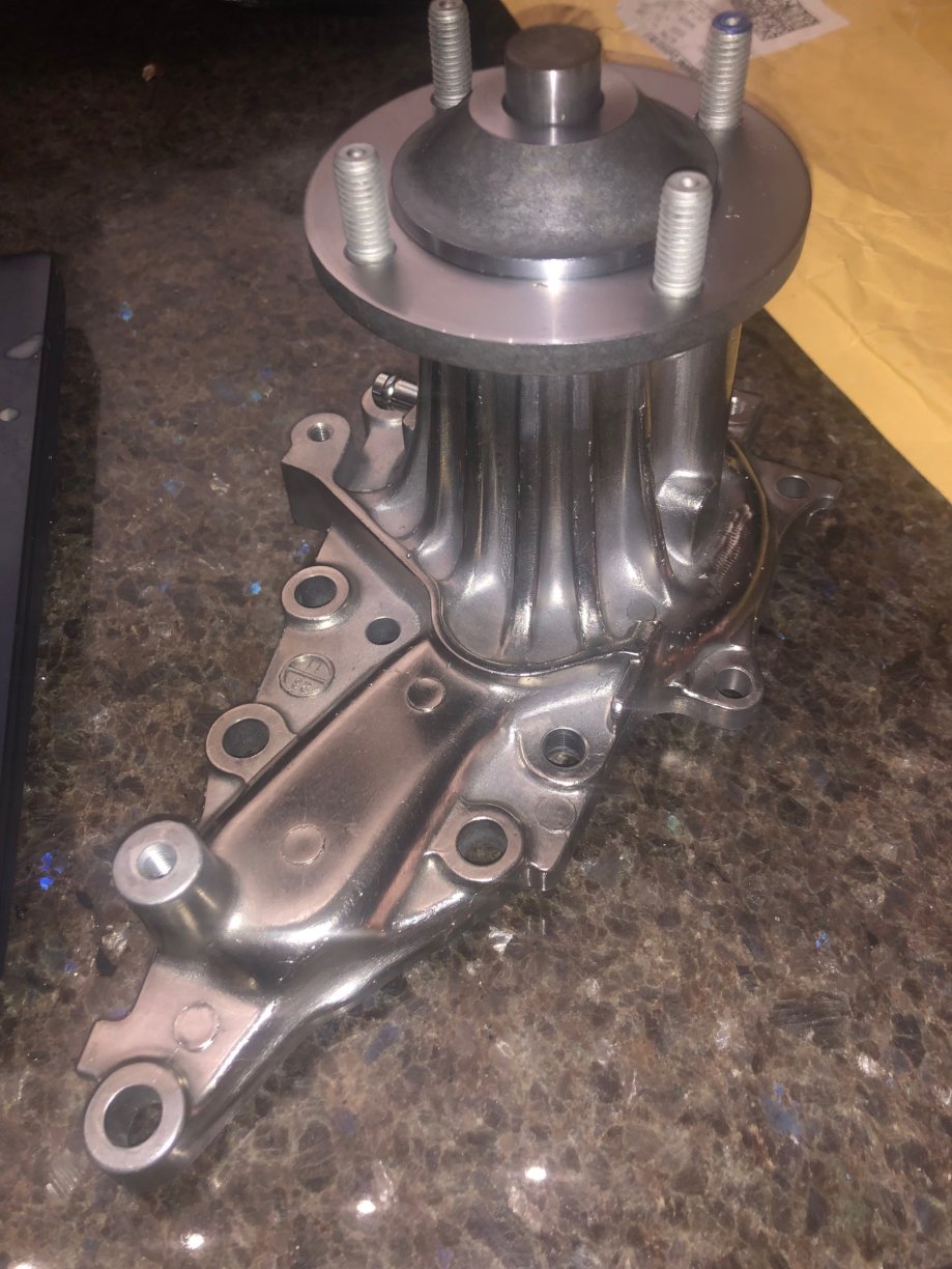
mine is the same - often OEM go to manufactures and say they want a timing belt …..say 250.000 for the assembly line and 20000 as spares for dealerships . Deal is done at say £10 a belt . They retail them for say £75 each . But they insist the belt has a length no other car uses , and it has a logo ,and they get sole supply for 5 years . After the 5 years the aftermarket can buy them for £25 each and sell for £50 . But the logo is removed . The water pump is cast and has a logo/part number or such specific to Toyota …..so they etch out the logo . They have to do this due to people …….your water pump has destroyed my engine type claims against OEM dealerships
-
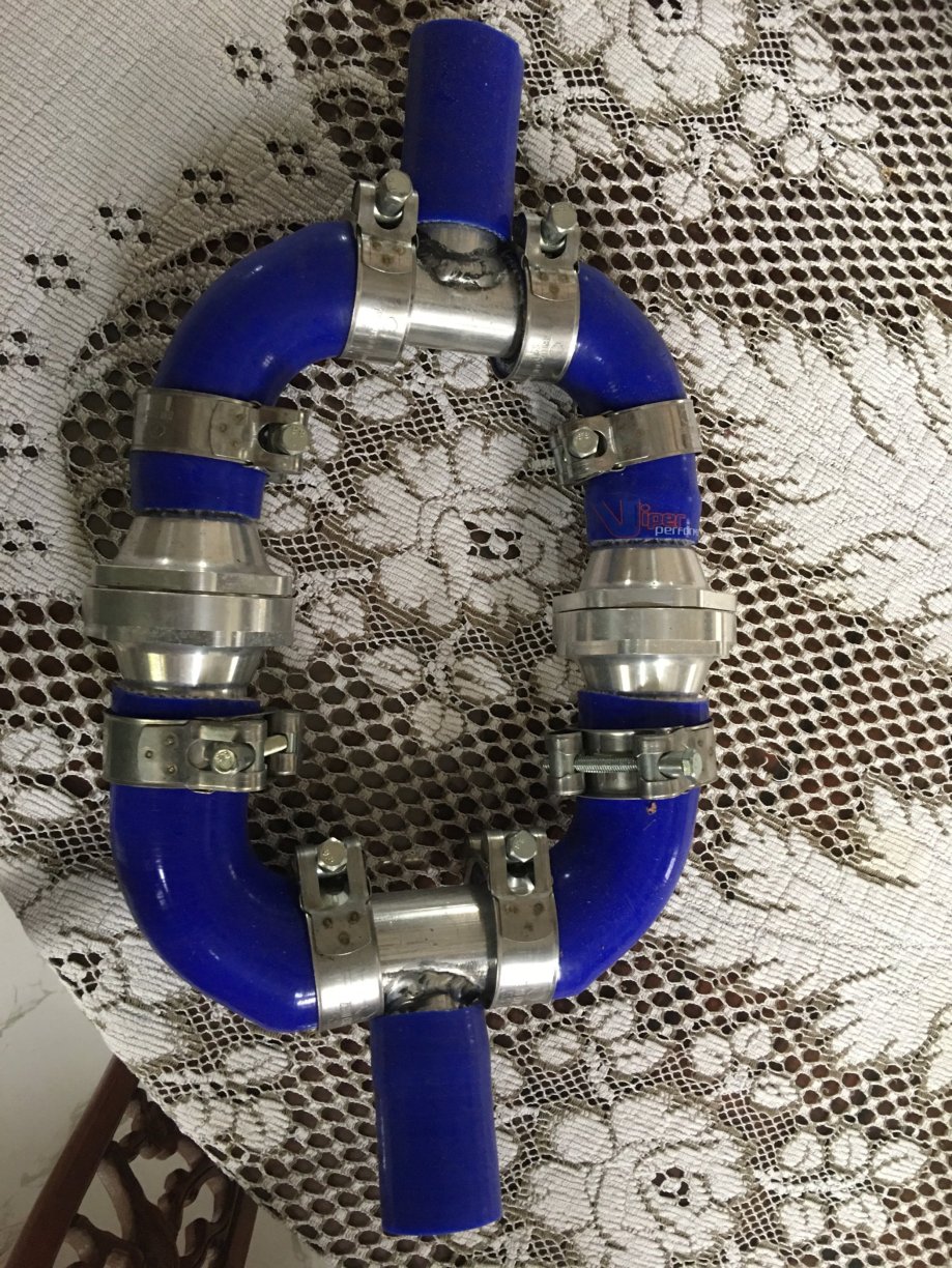
Removed the 255 fuel pump and fitted a new 450 Walbro pump -switched on the ignition and ….nothing . Bypassed the fuel pump Ecu from the diagnosis port FP …..and the pump runs smooth as . So the FP Ecu has finally died (it had hot start issues previously) so a bit of wiring needed to by pass the ECU and add a new relay and heavier gauge wire to the FP to battery . Top tip : the connector at the fuel pump cover is the weak spot in the wiring , the pins are open (no insulation) hence connector plastic melting - fill void with RTV. Next up trying out my own head cooling mod using twin external stats - not seen this tried before - see pic
-
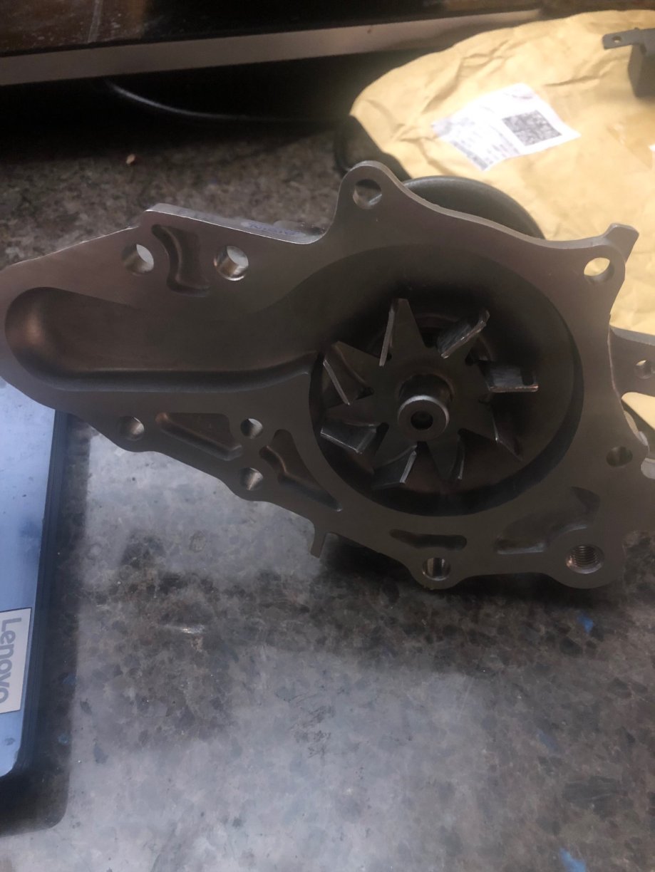
Just got one - has a metal impeller and comes with gasket
-
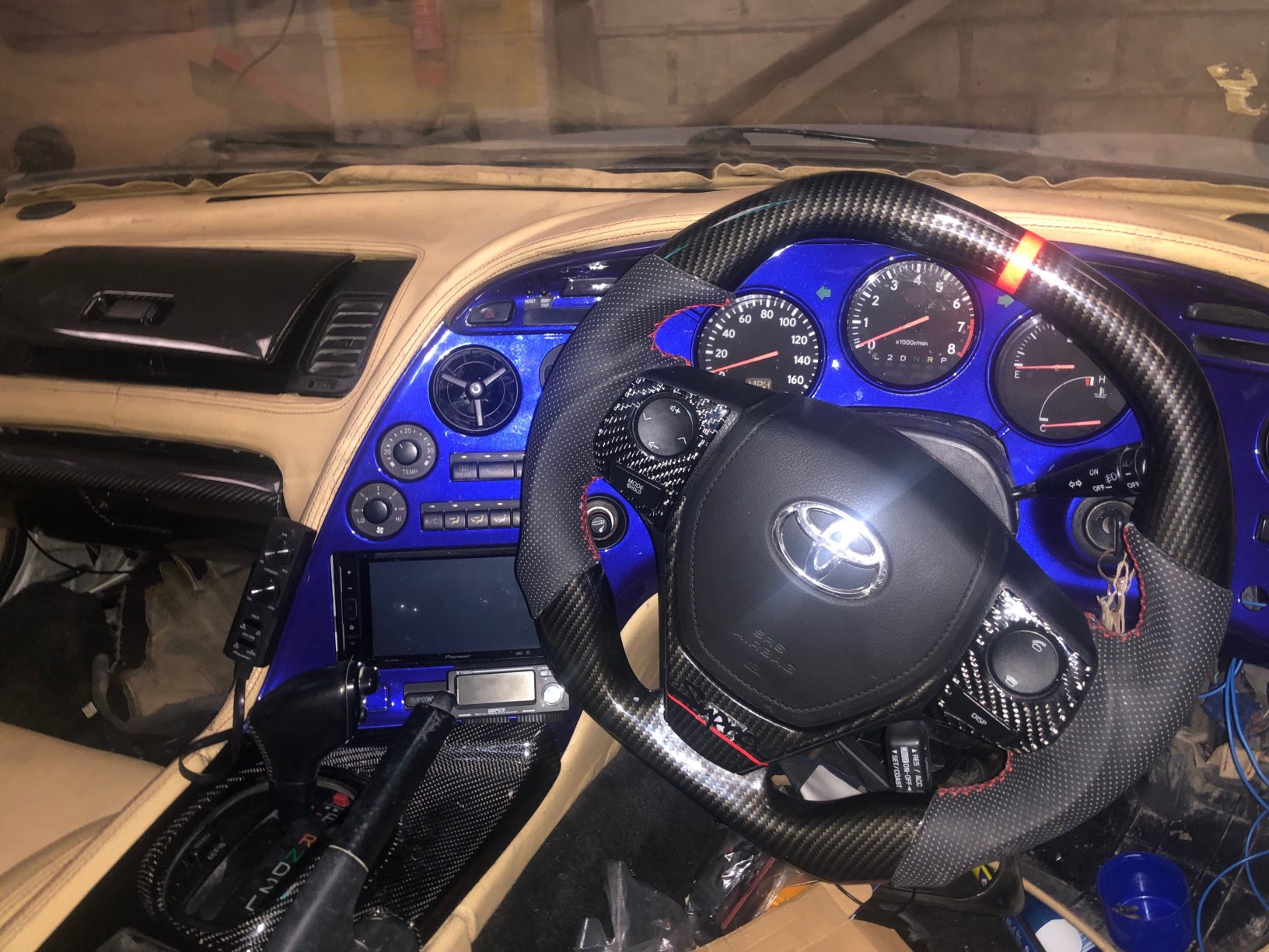
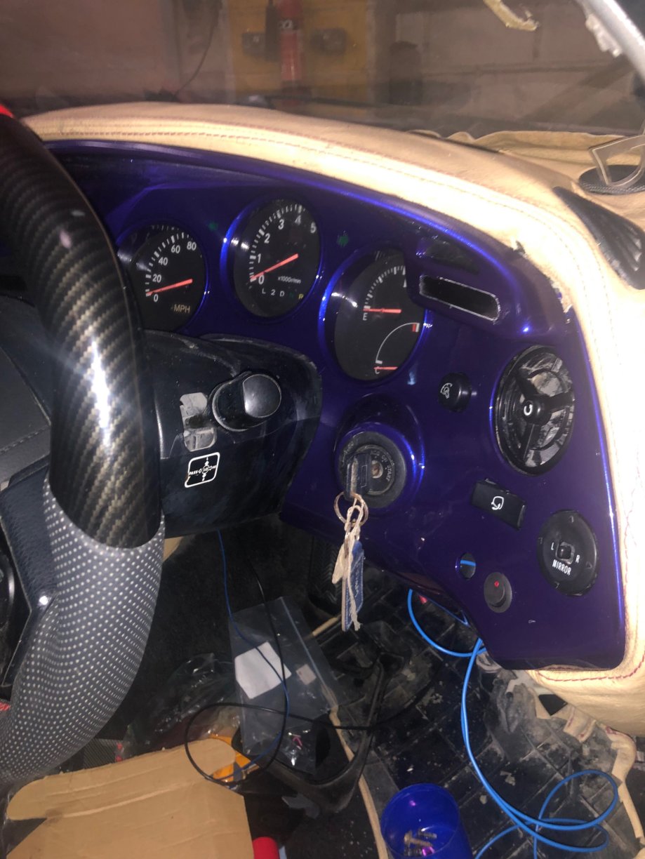
Dash going back in , so into a new year to finish off . couple of new things to try out ,that I’ve not seen on a supra before ,and see what data they provide 1 a CHT system and 2 a modified water stat system . See what data comes from them ?
-
About 10 years ago I did some testing - the stock intercooler pipe work is rubber/plastic ,aftermarket pipe work is usually aluminium . Aluminium absorbs heat about 1000 times what plastic does . I inserted a temp probe into the coupler of the up pipe behind the radiator and a digital gauge . then tested on road : the radiator heat out the rear of the rad was heating the air inside of the pipe . At low speed or stationary the temp rose dramatically, the faster you went the temp dropped .The FMIC worked quite well , especially at high speed but there was a sort of “plug” of heat caused by the radiator ,heating the up pipe , it cleared with speed after a delay . Next I insulated the up pipe with as much insulation as I could squeeze in the gap between the rad and the pipe It made a large difference in the air temp over the delay time period ,somewhere around 40 + degrees C is added by the up pipe absorbing heat from rad . But only at low speed So I thought the next step is to add a chargecooler into the up pipe ….heat is best removed at source ,ie pre turbo water injection ,but it has issues . Next is heat exchange via intercooler or charge cooler ,both will work and both work best at the highest temp diff . Using a chargecooler post intercooler is less efficient due to lower temp diff , but it will still exchange heat . downside is an increase in turbulence and slight pressure drop but it will remove the pipe heat off the radiator and drop IAT with a more constant output temp . In /out temps will show the drop on a gauge . And a dyno should show torque change with pump off and on and ice in tank . the stock IAT sensor is in the inlet manifold and will suffer heatsoak , how this is scaled with the Ecu and at what temps it pulls timing ,I don’t know …..but if I know the temps are constant and low at all times - this can be scaled back . I have not read of anyone trying combined cooling fmic and chargecooler so no data is available - so I’m giving it a go and see what happens - maybe it’s insignificant, who knows ?
-
MMO has been around forever , what’s in it has never been revealed , but it is pretty much a form of ATF . ATF has a high detergent cleaner level as will MMO - this is as it is used in autobox and auto trannys have very small internal passage ways and tiny ball bearing valves /solenoids- if these clog or stick the tranny fails . So the fluid has a high cleaning level to remove carbon from sticking to surfaces . So adding MMO helps cleaning things like tappets /rings / valve stems . On older engines using a non synth oil - they get sludge build up - so MMO was used as an oil flush ,prior to an oil change . It won’t fix a worn /knackered engine but it does clean well in both oil and fuel systems . If parking up a car for years - a squirt down the bores keeps the top ring from sticking - then hand crank before using the starter blowing out the oil .
-
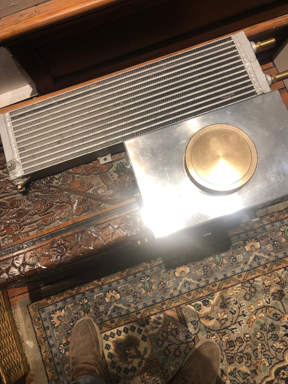
A bit more done - pulled out the spark plugs and put some marvel mystery oil down the holes - left it for 2 days and some in the top end . Hand cranked the engine and it was smooth as silk . Then spun engine on the starter - again perfect . Compression check - mint . Back flushed the heater core and it was super clean , put some rad cleaner and hot water in and flushed it - again clean as a whistle . So looked at the fuel system - removed fuel pump hangar and drained the tank - fuel was a yellow colour (around 4 liters) but the tank was like new inside ,no debris or rust - perfect new plugs ordered and fitting a bigger new pump - I removed the air con rad - knackered - so now have room for the chargecooler rad - they are different from normal hot water rads as they deal with much lower temps . and the header tank can go in the boot now . The tank has a large filler to allow ice to be used . I am fitting a gauge to look at pre and post chargecooler temps in the A pillar (more wiring) , the pre cooler temp will also be the post fmic temp . Just to see what happens with cooler running .
-
50lb is about correct for that size stud , at work we always used molykote mso2 , molybdenum grease - just a dab - it will help with dissimilar metals - titanium into aluminium and allow them to be removed again over time -just drop the torque by 10% . there are a few things that bolt into jet engine hot areas ,engine cases etc and we always use a grease - used to be ease off 990 a nickel based grease but there was a move away from that - any seized bolt in a case that causes damage is around 1million quid ! When you start leaning on a socket to remove - it gets tense -lol
-
Nice looking manifold , do you have any feedback using titanium bolts ? I have used titanium fasteners before in aviation ,they are seldom used ,and pretty much always into titanium . Usually around jetpipes as they get so hot and titanium is common as it’s strong and light . But we always used special sockets , normal chrome vanadium are not used , I forgot why , getting old - lol . Also expansion rates between head / manifold /and bolts will differ- would this be an issue? Along with different torque values .