
Andy Blyth
-
Posts
564 -
Joined
Content Type
Profiles
Forums
Store
Blogs
Events
Downloads
Supra Articles
Gallery
Everything posted by Andy Blyth
-
Yes there was a distinct difference in the spray quality as the pressure was varied. At the lower pressures (1.5 and 2 bar) the flow was mainly in two jets without much "spray." As the pressure reached 3 bar, the jets turned more into a cone of spray with better atomisation. At 4 bar it was even more pronounced - to the extent that I would be tempted to run 4 bar rail pressure before moving to "550 cc" injectors. As a little bit of a play at the end I ramped the pressure to over 6.5 bar and saw a powerful cone of good spray when the injector was held open. When I tested it with a 50% duty cycle, the flow seemed to be much lower than at 3 bar (unfortunately I didn't get any measurements) suggesting that the dead time went through the roof. This would make them a nightmare to control.
-
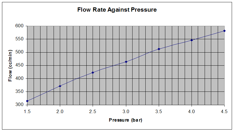
It's possible to do a quick back-of-an-envelope calc for this. Assuming a Brake Specific Fuel Consumption of 0.65 for a intercooled, turbocharged petrol engine we get: 0.65 [lbs/bhp.hr] = 0.295 [kg/bhp.hr] = 0.0492 [kg/bhp.hr] per injector = 8.207 E-4 [kg/bhp.min] per injector = 1.108 E-3 [litres/bhp.min] per injector (assuming density of 0.741 kg/litre from V-power datasheet) = 1.108 [cc/bhp.min] per injector. At 3 bar (standard FPR pressure) you are flowing 465 cc/min, therefore you should be able to support (465/1.108) = 420 bhp. At 4 bar you are flowing 546 cc/min, therefore you should be able to support (546/1.108) = 493 bhp. If you get less conservative and use a BSFC of 0.6, the power figures become 455 bhp and 534 bhp for 3 and 4 bar respectively.
-
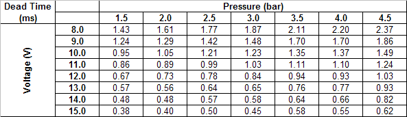
Yes, just different names for the same thing. Basically it's the correction that an ECU has to apply to the command going to an injector to account for the mechanical effects. For example, if you had a rail pressure of 3 bar (compared with intake manifold pressure) and a battery voltage of 14V, the dead time would be 0.58 ms (from above). If the ECU determined that at a particular engine speed and load that it wanted 2 ms worth of fuel, it would have to command the injector to open for 2.58 ms to get the desired fuel quantity. If it only commanded 2 ms, it would only get (2 - 0.58 = 1.42) ms worth of fuel and the mixture would be leaner than expected.
-
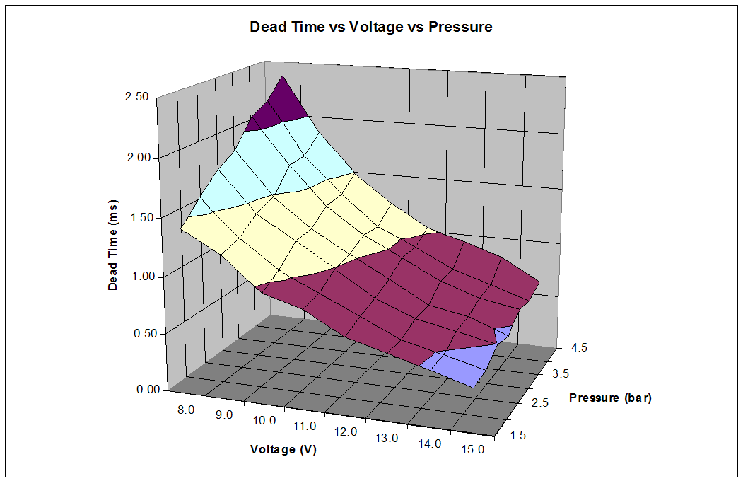
With a bit of spare time, I set up a test rig this afternoon to characterise the stock 440cc injectors, as part of my move to a standalone ECU. First up is a measurement of the injector flow at a range of rail pressures from 1.5 bar to 4.5 bar: The measurements were taken by using an adjustable fuel pressure regulator to set the rail pressure with one injector on (the pressure is different with the injector off and on due to the design of the FPR). For each test, the injector was opened for 30 seconds into a 250cc graduated cylinder. The cylinder was marked every 2cc so the best measurement I could take was to the nearest cc. Each reading was doubled to get the flow in cc/min. The next bit took forever! I set up a standalone ECU to open the injector at 50% duty cycle at a frequency of 50 Hz (equal to sequential injection at 6000 RPM) for 40 seconds. This was carefully chosen to maximise the use of the graduated cylinder and to maximise the effect of the injector dead times to improve accuracy. I applied a bit of maths to the volume measured compared to the expected volume in the ideal case (i.e. no dead time) to calculate the dead time. The pressure was varied between 1.5 bar and 4.5 bar again and the voltage was varied between 8V and 15V - this should also account for dead times during cranking. The calulated dead times based on my measurements are as follows: In picture form: As you can see, the graph isn't perfectly smooth. I believe this is due to my measurements only being made to the nearest cc. For some of the "strange" points, I retested to ensure that the result was repeatable. I've given the "raw" measurements so that you can choose to apply some smoothing of the data if you wish.

-
Again, I'm not sure how it works with the systems on the N/A; on the TT, the fuel pump is powered only when the engine is turning or for a few seconds after the key is moved to the ignition position to prime the pump / rail. I agree that it's potentially dangerous to run the pump at any other time so I checked this behaviour when adding the relay on my car. Cheers Andy
-
I use the blue with red stripe wire coming out of pin 2 of the fuel pump ECU to power a relay. This is the wire that normally goes to the stock fuel pump. Works a treat. However, this is on a TT, I'm not sure which wire it would be on a N/A.
-

wanted Low amperage clip on current clamp for oscilloscope.
Andy Blyth replied to Chris Wilson's topic in Other Items
The "software attenuation" function is for use with attenuated probes. Back in the Good Old DaysTM if you used an attenuated probe, the signal you saw on the screen would be different to the signal that you were measuring. For example, if using a x10 probe you probed a 20V DC signal, your scope would show 2V DC. You would have to remember to multiply the signal by 10 in your head to get the real signal. There are a few reasons you may want to use an attenuated probe: one being to look at signals that are greater in amplitude than your scope can handle, another is when you want to measure particularly sensitive circuits - attentuated probes have a higher input impedance and draw less current from the circuit being tested at the cost of a lower signal to noise ratio. With the advent of digital scopes, you no longer have to perform the multiplication in your head - the scope can do it for you. Basically you need to set the "software attenuation" to match the attenuation of your probes. Here, even though the 20V original signal is attenuated to 2V at the input of the scope, the software will display a 20V signal. It's important to ensure that the software is set to match the attenuation of the probes to ensure that you aren't misled by the measurements. Many probes have a x1 / x10 selector switch; it's easy to lose track of which setting each probe is on. The scope you have is more than capable for automotive work! The signals encountered in the automotive world aren't particularly demanding for an oscilloscope. Even full-speed CAN bus can be viewed with a bandwidth of 2MHz. The features I concentrated on when selecting a scope for automotive use were the physical robustness of the scope, how user-friendly the software was and the different triggering options. -
wanted Low amperage clip on current clamp for oscilloscope.
Andy Blyth replied to Chris Wilson's topic in Other Items
Thanks Chris. I use a PicoScope 3204. It's a little underpowered for the embedded electronics work I do but more than capable for automotive work. The only thing that lets it down is the low max input voltage of +/- 20V. When used with a x10 attenuating probe this only gives you a +/- 200V range, unsuitable for hooking up to ignition coil primaries or mains powered circuits (340V peak). I've got around this by buying a couple of x100 attenuating probes from a seller on ebay which are rated to 1.2 kV. It's a good job too - when I was measuring the stock coil primary voltage, I saw voltages of 450V when the coil current was cut, peaking at 750V when the spark started. I didn't realise Dataman made oscilloscopes! I only know them from their EPROM programmers. The model you have looks like quite a capable scope, better than the Pico Automotive scope in most areas, especially sampling rate and bandwidth. The Pico has a 12 bit resolution vs. the Dataman's 8, but in my experience I've never needed better than 8 bit resolution on a digital scope. The biggest advantage that the Pico scope has is it's sampling buffer - It can store 32M samples compared with 8k on the Dataman. I'm a big fan of large buffers on digital scopes as they are invaluable in finding glitches in digital logic circuits. However, I don't think they are as valuable in an automotive environment. -
wanted Low amperage clip on current clamp for oscilloscope.
Andy Blyth replied to Chris Wilson's topic in Other Items
All this talk of current clamps motivated me to pull my finger out and buy one. I went for the Pico one in the end; it arrived today. One of the first things I went to measure was the ignition dwell time with the stock ECU and stock coil packs. I was quite surprised by the waveform I measured: It appears that the stock igniter is regulating the coil current at around 6.6A. I didn't expect to see this. As a quick comparison I hooked up a single channel igniter to a stock coil and drove it with a standalone ECU. It appears that this igniter is also limiting the current, but to a lower value of 5.4A: I believe on your Skyline you chose to replace the stock Nissan igniter with a couple of 3-channel igniters (I came to the same conclusion for my standalone build). If you're desperate to play with your new current clamp would you mind clamping it around a wire going to a coil pack and posting the current waveform you see? If the 3-channel igniters are limiting the current I need to re-think my system. Cheers Andy -
wanted Low amperage clip on current clamp for oscilloscope.
Andy Blyth replied to Chris Wilson's topic in Other Items
Hi Chris I've been looking for something similar myself recently. I've had my eye on the PP264 from Pico for a while. I've not come across anything close to it for automotive type work. It'll do both AC and DC; it also has a 20 kHz bandwidth which will come in handy for fast transients in ingition systems. Cheers Andy -
That looks like the harness side connector for the crank position sensor - it's fairly important!
-
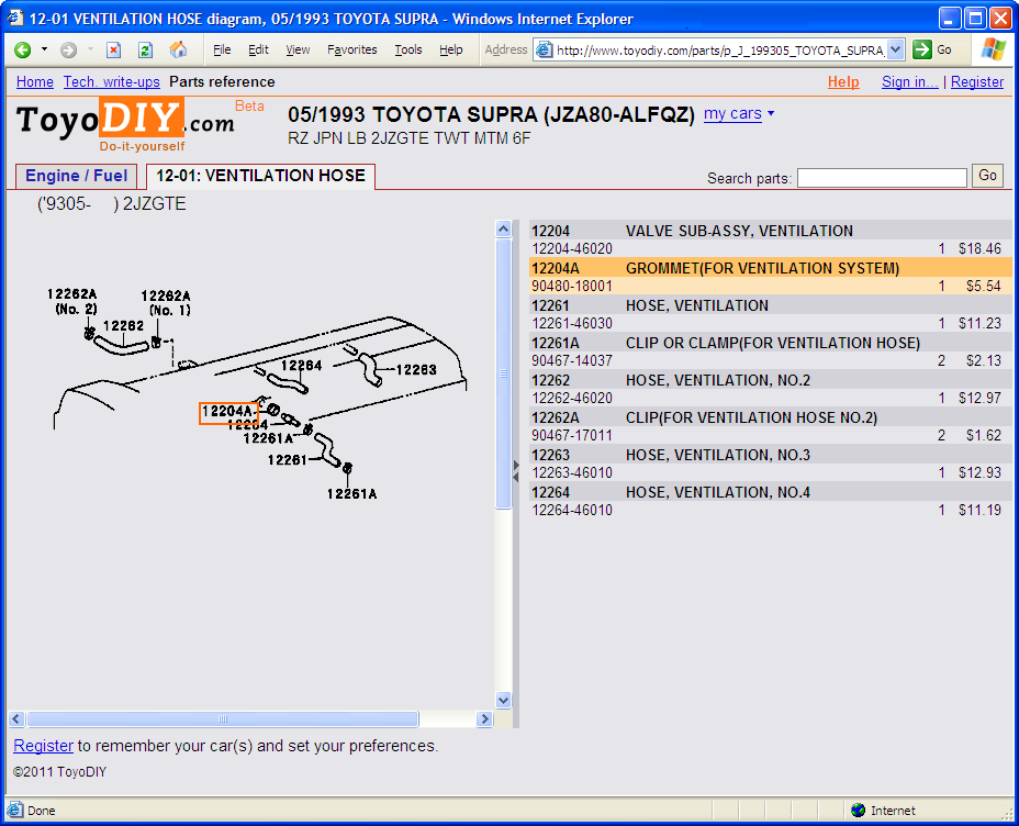
90480-18001?
-
-
Did you have any your alarm / immobiliser disarmed when you tried to read the codes? The MIL should flash on and off with even spacing if there are no codes stored; it shouldn't stay off completely when the TE1 and E1 terminals are connected together. If the car is immobilised then the ECU won't be receiving power and won't turn the MIL on when tested.
-
It's a return line, so low pressure.
-
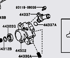
I can think of only 4 points where air could get into the system without oil escaping: the hose barb on the bottom of the reservior, the suction hose itself, the hose barb on the suction side of the pump and the o-ring on the hose fitting of the suction side of the pump. (44337A on the below image) My money would be on the o-ring. Only a couple of quid to replace.
-
sold Whifbitz Side-Mount Intercooler (SMIC)
Andy Blyth replied to Andy Blyth's topic in Parts for Sale
Sold now. Thanks for the interest guys! -
You'll be fine. The two connections are the same. The three pin connector is in a slightly different place (one is round the back, one is on the side but I can't remember which is which) but the harness is long enough to reach.
-
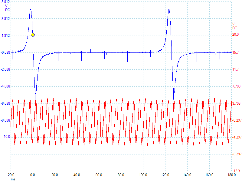
This is a capture of the crank sensor (red) along with one of the cam sensors, engine idling:
-
sold Whifbitz Side-Mount Intercooler (SMIC)
Andy Blyth replied to Andy Blyth's topic in Parts for Sale
Asking price reduced! -
That's not a picture of my car. However, the line is supported by two pieces. One is the bracket that is bolted to the subframe, the second is a small clip that is bolted to the bracket. The small clip should come with the braided hose as it needs to be threaded onto the hose before the ends are crimped on.
-
sold Whifbitz Side-Mount Intercooler (SMIC)
Andy Blyth replied to Andy Blyth's topic in Parts for Sale
Still available! -
Yeah, there are TE1 and E1 terminals in the circular diagnostics connector below the steering wheel, next to the bonnet release. Their positions are shown on the back of the connector's cover.
-
Are you getting any fault codes?
-
I have a used Whifbitz replacement SMIC available. I'm looking for £265 including postage by special delivery. I fitted it just over a year ago but one of the seams recently began to open up. It has been back to Paul to have the seam welded up by the company that originally made it. They have also checked the intercooler over and gave it a clean bill of health. The fins etc. are in a good state. Much better than an old stock SMIC! Here are some photos; the last one shows the repair: Click the thumbnails for a larger picture; click again for full resolution. It's sitting in a box ready to go if you're interested.


