
Andy Blyth
-
Posts
564 -
Joined
Content Type
Profiles
Forums
Store
Blogs
Events
Downloads
Supra Articles
Gallery
Everything posted by Andy Blyth
-
The thick blue wire with the orange stripe is the switched 12V feed to the pump ECU. The thick blue wire with the red stripe is the feed from the pump ECU to the fuel pump. The thin violet wire with the white stripe is the control wire from the main ECU to the fuel pump ECU.
-
In the past I've been tempted to drive a relay using the stock control wire from the ECU as you describe but in the end I decided against it as I was unsure of the rated current capability of the stock ECU, and was too lazy to measure the current in the stock setup! In the end I used the fuel pump ECU output to drive the coil of the relay, with the logic that if it can support the current of a fuel pump, it can manage a relay. It works well. I noticed a few clicks of the relay as the engine starts to crank, but after that the relay never dropped out either in idle, vacuum or boost. The setup was quite similar to that in post #44, only I used the stock 12V feed to the pump ECU instead of running a new supply. I must take some time to open up a stock fuel pump ECU one day; sounds like there is more in there than I expected!
-
Yes! What is key in EFI applications without fuel pressure feedback to the ECU is to have a constant *differential* pressure across the injectors to keep the average flow rate for a given injector pulsewidth constant. When we say we set the fuel pressure to 3 bar, we're saying that the pressure in the input end of the injector, minus the pressure at the output end of the injector is 3 bar. The fuel pressure is normally set with the engine not running, so the output side of the injector is at atmospheric pressure. 3 bars (input) - 0 bars (output) = 3 bars (differential). A pressure gauge is also giving a differential reading relative to atmospheric pressure so it will indicate 3 bars. When the engine is started it draws a vacuum in the intake (and therefore at the output of the injectors) of e.g. -0.5 bars, results may vary. In this case we still want a differential pressure of 3 bars, the FPR will drop the absolute rail pressure to 2.5 bars (gauge). 2.5 bars - (-0.5 bars) = 3 bars. You can verify this by watching a gauge connected to a fuel rail with the engine stopped (but pump running) and then with the engine idling. In exactly the same way, when boosting to e.g. 1.5 bars, the pressure at the output of the injectors is 1.5 bars (gauge) so the FPR will move the rail pressure to 4.5 bars to keep the differential pressure to 3 bars. 4 bars - 1.5 bars = 3 bars.
-
The easiest way to look at it is the pump provides hydraulic power. Hydraulic power is simply pressure x flow; in the same way that electrical power is voltage x current. The pump can be considered as a constant flow source (OK, it's not really as the flow drops off a bit with load) for a given voltage. When the FPR raises the line pressure with this fixed flow, the hydraulic power the pump is delivering is increased. This must be linked with an increased electrical power entering the pump; we're not going to be breaking the laws of physics here! As the voltage supplied to the pump is constant (ignoring supply cable voltage drop) then the current drawn by the pump must increase to give the increased electrical power.
-
I'm not sure; I'm not using it with the stock hanger. When the connector is installed into the hole, you need clearance around the hole for the o-ring and also to the side the connector comes out. If you zoom in on the picture, you can see a support moulded in to the yellow piece. I guess you could trim it off with a knife if it got in the way.
-
I can certainly recommend these harness kits: http://www.racetronix.biz/itemdesc.asp?ic=BCWS-001&eq=&Tp= Cheap as chips and only needs a 10mm (approx.) hole giving you 4 x 14ga cables in your tank.
-

Operation of first turbo on stock J-Spec manual
Andy Blyth replied to Andy Blyth's topic in mkiv Technical
It's taken a little while but I believe I've now found the culprit: The Exhaust Gas Bypass Valve is not attached to its actuator, leaving it to flap around and divert exhaust gases away from the first turbo. I've been wondering what that ringing noise when off boost was for years!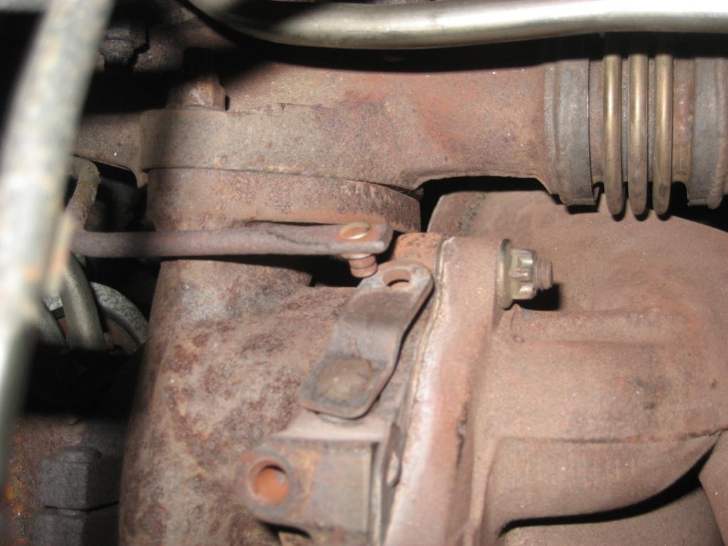
-
I've got a stock 6-speed pressure plate (bought from Toyota) in front of me and it's stamped AISIN if it helps.
-
The blue one, for the EGBV VSV is 90980-11156. The black one, for the IACV VSV is 90980-11149.
-
Hello Chris; I'll send you an email.
-
I think what Chris is trying to say is that when you mention 20.9, that is the percentage Oxygen content, by volume, of atmospheric air - not AFR. When you refer to an AFR of 22, that is the ratio of air (not Oxygen), by mass, to fuel. FWIW, I've found that the 2JZ will just about idle at an AFR of 22 (it's right on the limit - any leaner and it'll stall). In that condition, for every gram of fuel entering the engine, there will also be 22 grams of air entering. That air will have an oxygen content of around 20.9%. The air leaving the exhaust will have significantly less oxygen.
-
I don't think so. Each of the stock cam sensors give 1 pulse every other revolution of the crank, whereas the tacho signal is 3 pulses per crank revolution. However, the cam sensor is needed to give the ECU a reference position. Maybe the Syvecs ECU needs a position reference before it begins to give a tacho signal. I'm not sure, but it's possible. Thinking about it, with the 2JZ-GTE (non-VVTI) the fact that it fires at all tells you that the cam sensor is fine. Without it, the ECU wouldn't have a clue when to fire the spark plugs and the engine wouldn't run at all - even for a few seconds.
-
On the TT, it comes from the engine ECU.
-
Power Steering Rack - Return Line thread size
Andy Blyth replied to Andy Blyth's topic in mkiv Technical
Thanks very much for measuring Chris; it's much appreciated. -
Power Steering Rack - Return Line thread size
Andy Blyth replied to Andy Blyth's topic in mkiv Technical
Thanks Chris. I'm in two minds at the moment. Either I'll get a banjo fitting directly on the end of the line or use a fitting that converts a metric (?) thread into a -6 AN thread then use a normal AN Teflon fitting. It really depends on what the clearance is like around the banjo; If there's little clearance then I'll struggle to get a Teflon banjo fitting in there. I'd better get my torch out and have a little look! I'd really appreciate it if you're able to get the diameter and pitch of the bolt. Andy -
Does anybody know the thread size of the return line fitting on the power steering rack? I've made a few searches but without finding any info. The one I'm referring to is the line that goes between the steering rack and the stock power steering cooler. It's a banjo fitting. I'm asking as I want to replace the line with a braided Teflon line when I replace the cooler. Thanks Andy
-
2JZ-GTE VVTi and none VVTi part numbers wanted.
Andy Blyth replied to Chris Wilson's topic in mkiv Technical
Hello Chris, the Crank Trigger Wheels are different on the VVTI and non-VVTI. The non-VVTI has an evenly spaced 12 tooth trigger wheel; the VVTI has a 60-2 tooth wheel. The VVTI oil feed part numbers are shown in the attached picture.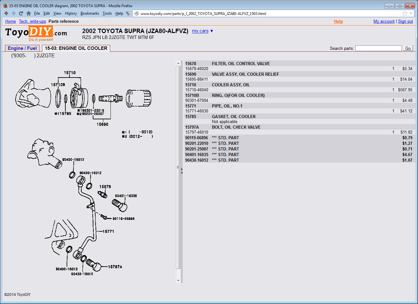
-
Exclusive! JDM Supra (JZA80 MKIV) Wiring Diagrams
Andy Blyth replied to beast_drc's topic in mkiv Technical
Wow! That's excellent work Alex. That will come in really handy; it's something I've needed for a while - Spasibo! -
You have some strange readings, especially for test 4 and test 5. Please could you measure the resistance (with the engine not running, everything turned off) between the alternator casing and the battery negative terminal? It should be significantly less than 1 Ohm. You may struggle to make a meaningful measurement with that multimeter but the reading you make could give us a clue. Make sure that you are getting a good contact to the alternator casing with your probe by scratching through any corrosion. It is probably a good idea to check for the presence of the main grounding cable between the battery negative terminal and the engine block. It should connect underneath the intake runners.
-
The housing part number is 90980-11153. If you need the terminals too, their part number is 82998-12790 (they come already crimped to 500 mm of cable).
-
The bottom pipe (outlet) of the radiator should be cold. It means that the radiator is doing its job. HTH
-
You could quite easily test your theory without changing the gasket. Install a switch in the cabin that replicates the "paper clip" method of forcing the fuel pump to operate (bridging the FP and B+ terminals in the diagnostics port connector). Wait until you are expecting the car to have trouble starting. Before you try to start, give the fuel pump a 5 second blast (using the switch), which should be enough to force any vapour out of the rail and into the tank. I think the following caveats would apply: 1> You would have to try this many times before beng able to have confidence that priming the fuel rail "fixes" your problem (you can't accurately predict the behaviour before it happens). 2> Doing this would replace the fuel in the rail with cool fuel from the tank. This may have an effect on the behaviour of the fuelling system. Hot fuel is lower in density; also the response times of injectors goes up with temperature (higher resistance). 3> Priming the fuel system will ensure that the fuel rail is at a sensible pressure at the point at which you start cranking. It's possible that your fuel rail has no pressure after 20 mins if you're running an aftermarket FPR. this could have an effect on the cranking behaviour. Do you have the ability to measure the temperature that the IAT sensor sees after a long heat soak? I'm running a stock ECU at the moment and after a hot start, the AFRs are very lean when idling, until the closed-loop fuelling starts. When running a standalone, I can see the stock IAT sensor sees some crazy intake temperatures after a heat soak. That said, I'm not sure if the stock ECU looks at the IAT to calculate the fuel needed for cranking.
-
It's for the low fuel level warning light on the dash.
-
If it went with a bang I'd start by looking at the release fork; it may have cracked. From memory, I think that if the release fork isn't there, there is nothing to stop the slave piston from leaving its cylinder which will quickly empty the fluid. I'd really recommend having a look to see what has broken before buying replacement parts. I've learned that lesson the hard way!
-
It's in the return line from the rack to the reservoir.

