
Konrad
-
Posts
4247 -
Joined
-
Days Won
2
Content Type
Profiles
Forums
Store
Blogs
Events
Downloads
Supra Articles
Gallery
Everything posted by Konrad
-
Get yourself checked with doctor, you might have a stomach ulcers...
-
You are talking about Sucker Punch Obviously this movie is quite simple and do not expect complicated plot, it's one of those "brain resters" At the same time - it does have a plot, action is quite fast and it keeps you entertained from start to end.
-
It's funny, light hearted and entertaining. Good crew with quite hot Jennifer Ariston Worth watching
-
solder is cracking and those lights fail to turn on at the start, just resolder and it will be fine
-
You will struggle to get opinion from people as (like any intelligent human being) we do not like to put hand onto fire 10 times. 6 is enough for most fact is, that no matter how enthusiastic you sound, MS tend to repeat same old story with screwing up anything they touch. IMHO Windows 98se and xp pro are only reasonable products they gave to public. It absolutely pointless to create new mobile system, they should embrace what's on the market already. I just hope that HTC andc others will get cold shower AGAIN and ditch stupid idea of ms on their phones.
-
Oh dear, this "completely neutral" bloke is raving about Windows system again? mate you sound like bloody ms advert, leave us alone, go with this commercial mumble somewhere else. There are better ways to gain money you know? Like sweeping slaughterhouse or something.
-
Make sure again if grey and white are at their proper place, there are few additional sockets in the passenger footwell and I know from own experience that white plug will fit to at least one redundant socket on the left side.
-
I assume motorbike gangs and their behaivour towards general public have a lot to do with people seeing them in certain way Did you like an advert anyway?
-

looking for HKS Super SQV mounting flange & recirculation kit
Konrad replied to fastnfurious's topic in Parts Wanted
Wrong forum mate, you need to put it at Wanted section -
Because of stereotypes. Think about your favourite EDL party and how it mix with black people. It's in Belgium tho, so people might be more laid back there
-
I think I have a airconditioning pump kicking around in the garage, if you will look for one
-
Biggest respect for black couple, balls from steel
-
RS3iB47nQ6E
-
To be honest, I would love to live in the house like this
-
well, you got proper "dimensions" to live there, Karolina, might struggle a bit
-
Oi mate, 7 posts and all in For Sale section? Go away, if you want to do bussiness here, contact mods first.
-
This little babe, tasteful U-1e7gocYi4
-
You can't, it should regulate itself. Did you have air conditioning on?
-
Yeah, it will be master brake cylinder most likely, or some air stuck around ABS unit if you have one.
-
MKIV clutch getting stuck to floor; master/slave cylinder or pressure plate?
Konrad replied to a topic in mkiv Technical
I think, that JamieP from this forum had exactly the same problem and it went away for a while after master/slave clutch cylinder change, but came back later. You might ask him or LeeP, who is taking care about his car. -
Oh and just to add, AFAIK NA and TT Jspec fuel pump is the same thing. When you open pdf file go to EG-277 and there is exact location of ground cable. SFI System - 2JZ-GTE.pdf
-
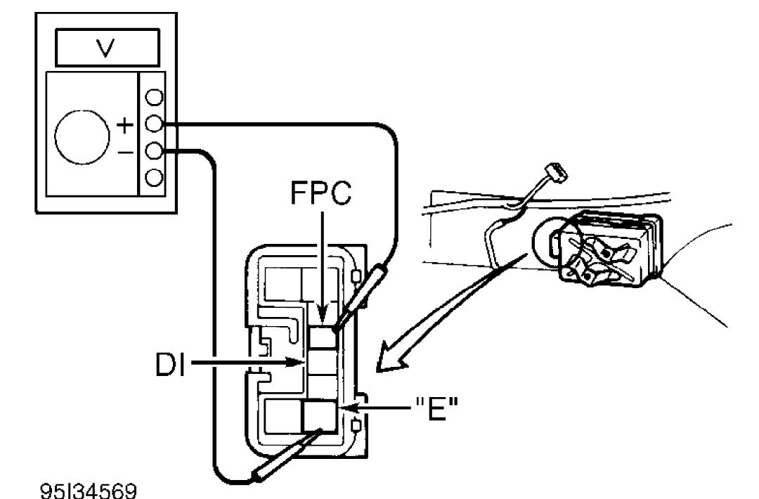
DTC 78 - FUEL PUMP CONTROL CIRCUIT CAUTION: If ECM replacement is instructed in following testing, always ensure ECM connectors and ground circuit are okay. If either are suspect, repair and repeat testing to confirm ECM malfunction. Circuit Description The 2-speed fuel pump is operated by the fuel pump ECU which receives a signal from ECM to compensate fuel pressure for start, light engine load or high engine load. DTC is set during the following 3 conditions: 1) Open or short in fuel pump circut is detected for 1 second or more with engine speed of 1000 RPM or less. 2) Open in input circuit of fuel pump ECU with engine speed of 1000 RPM or less. 3) Open or short in fuel pump ECU diagnostic signal line with engine speed of 1000 RPM or less. Possible causes for all conditions are: * Fuel pump ECU open or short circuit. * Fuel pump ECU. * ECM power supply circuit. * Fuel pump. * ECM. Diagnosis & Repair 1) Turn ignition on. Using jumper wire, connect DLC1 terminals +B and FP. See Fig. 11. Check if fuel pressure can be felt in hose to fuel filter. If pressure is felt, go to next step. If pressure cannot be felt, go to step 3). 2) Check for open or short in +B and FP circuits between DLC1 and fuel pump ECU. Fuel pump ECU is located back of left rear wheelwell, behind trim panel. See appropriate wiring diagram in L - WIRING DIAGRAMS article. Repaire as necessary. If circuits are okay, go to step 5). 3) Ensure ignition is on. Using DVOM, measure voltage between ground and DLC1 terminal +B. If voltage is 9-14 volts, go to next step. If voltage is not 9-14 volts, inspect ECM power supply circuit and +B circuit between DLC1 connector and main relay. See appropriate wiring diagram in L - WIRING DIAGRAMS article. Repair as necessary. 4) Inspect FP circuit for open or short between DLC1 connector, fuel pump and ground. Repair as necessary. If circuit is okay, replace fuel pump. 5) Access fuel pump ECU. Fuel pump ECU is located back of left rear wheelwell, behind trim panel. Disconnect fuel pump ECU connector. Check voltage between terminals "E" and FPC at ECU wiring harness connector. See Fig. 18. Turn ignition switch to START position. If voltage is 4.5-5.5 volts, replace fuel pump ECU. If voltage is not 4.5-5.5 volts, go to next step. 6) Inspect FPC circuit between ECM and fuel pump ECU for open. See appropriate wiring diagram in L - WIRING DIAGRAMS article. Repair as necessary. If circuit is okay, inspect "E" circuit between fuel pump ECU and ground. Repair as necessary. If both circuits are okay, go to next step. 7) Inspect DI circuit between ECM and fuel pump ECU for open or short. See appropriate wiring diagram in L - WIRING DIAGRAMS article. Repair as necessary. If circuit is okay, replace ECM and retest
-
You can always try 1JZ conversion
-
It's cheap enough to change it if you never done this job before. I change it during engine conversion anyway as there is a chance that there will be some particles around. Had same thing happening to my gf car and it was quite sudden.
-
I still insist on fuel filter check
