Leaderboard
Popular Content
Showing content with the highest reputation since 03/30/25 in all areas
-
I've also placed a large order with Ross Sport for replacement parts for my Alcon calipers. I've ordered new pistons, seals, anti-rattle clips and bridge pipes for all four calipers. I have CAR97 6 pot mono fronts and CAR98 4 pot mono rears. I'm going to media blast the calipers and then have them painted red with white Alcon logos.5 points
-
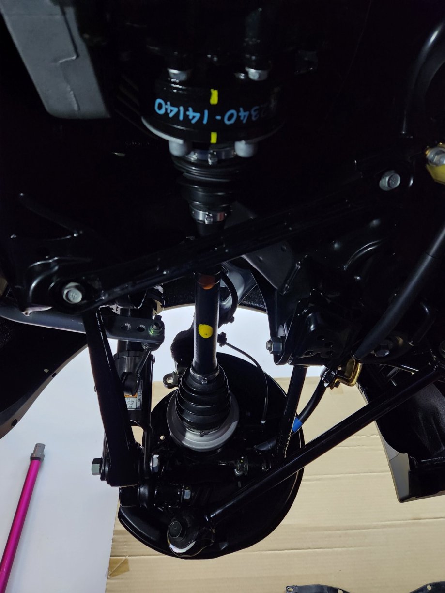
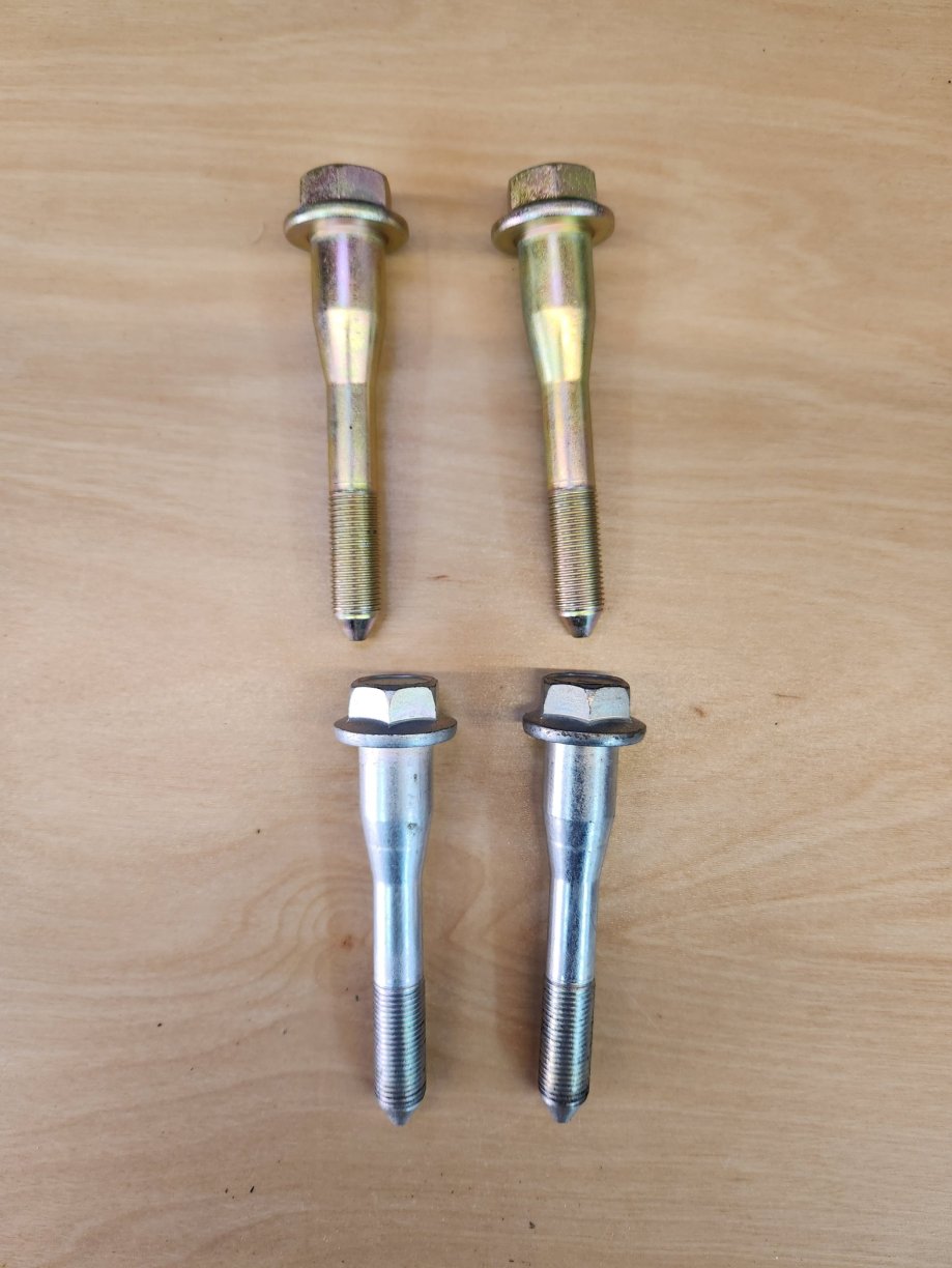
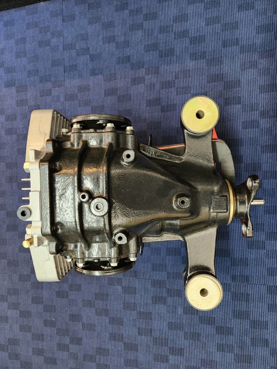
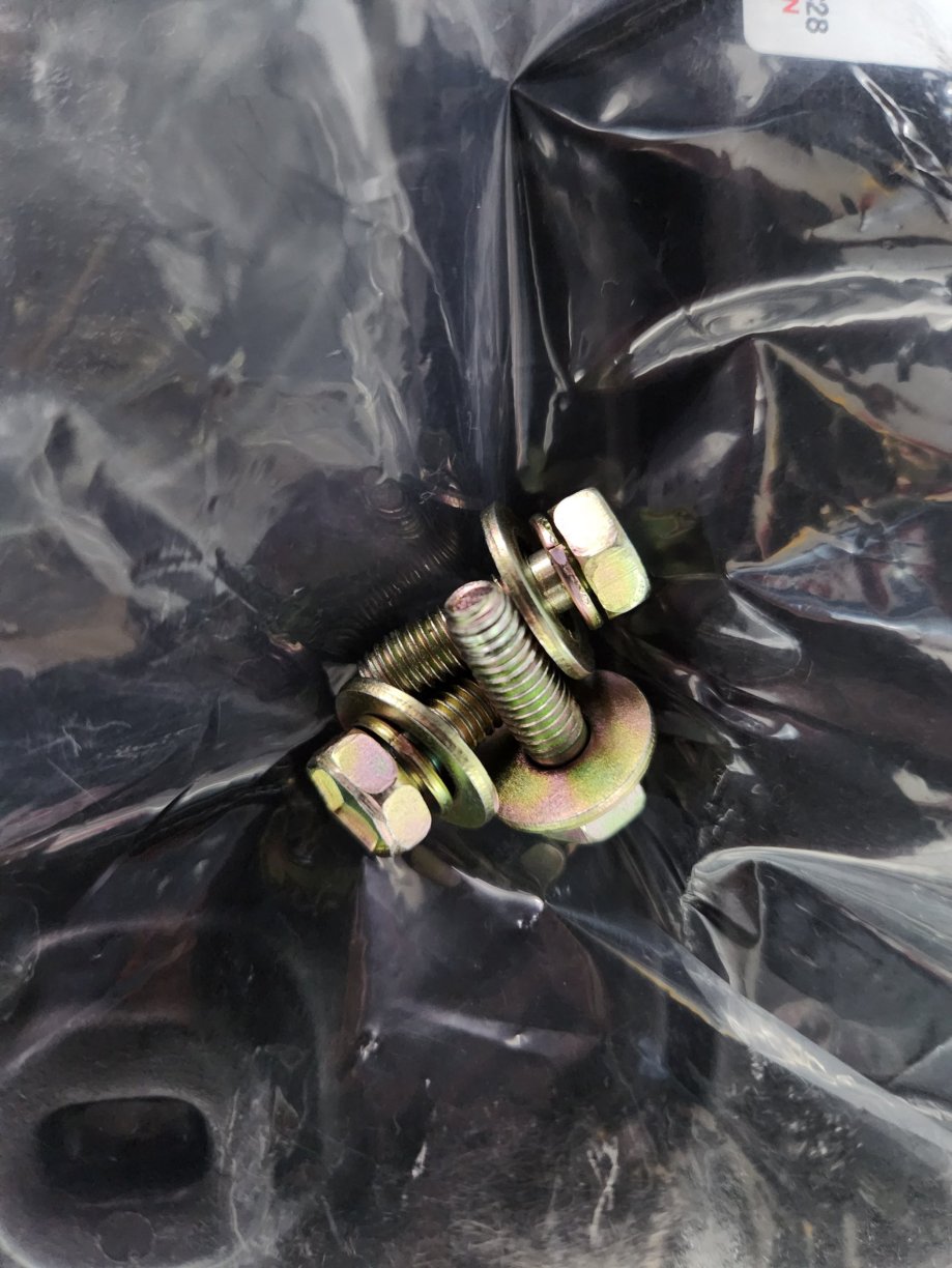
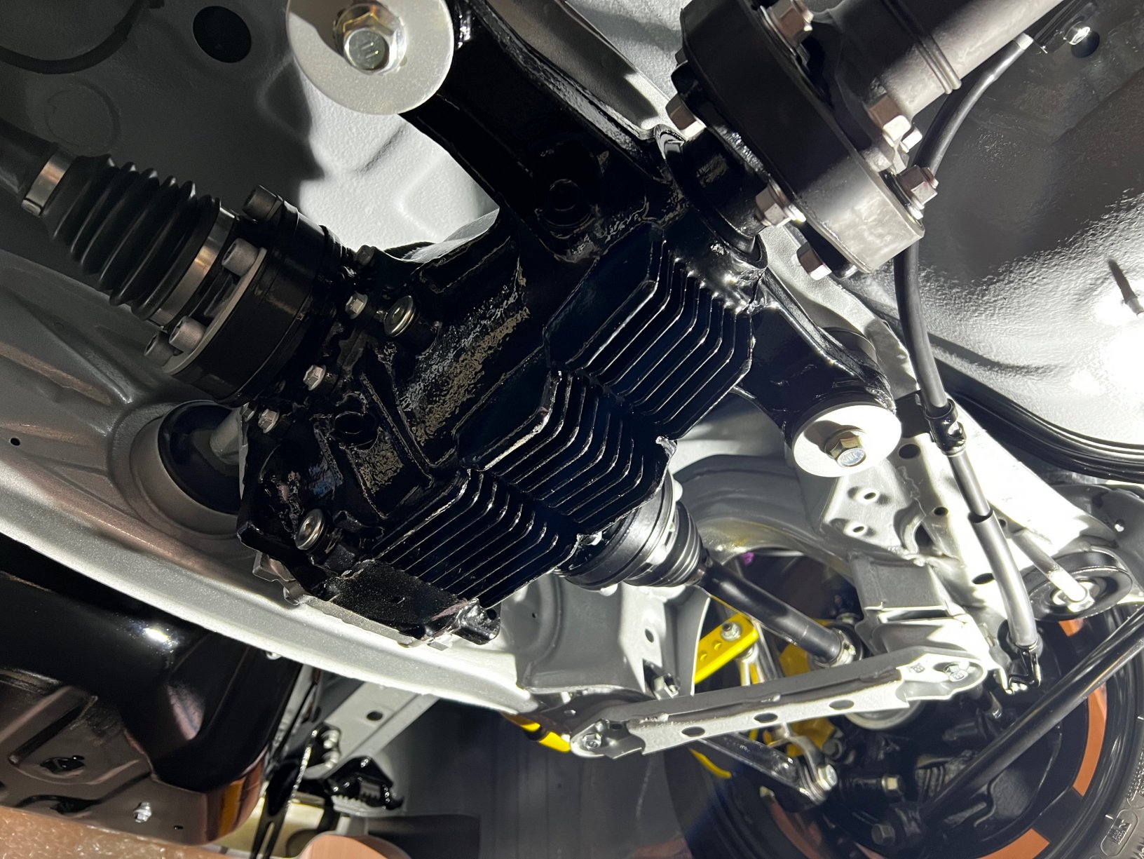
My rebuilt large case diff with TRD differential has now been installed along with the two new driveshafts. The diff ear bushes were replaced in the rebuild with Vibra Technics ones. I bought new OEM bolts and washers for the diff mounting and drive shafts. The new driveshafts.


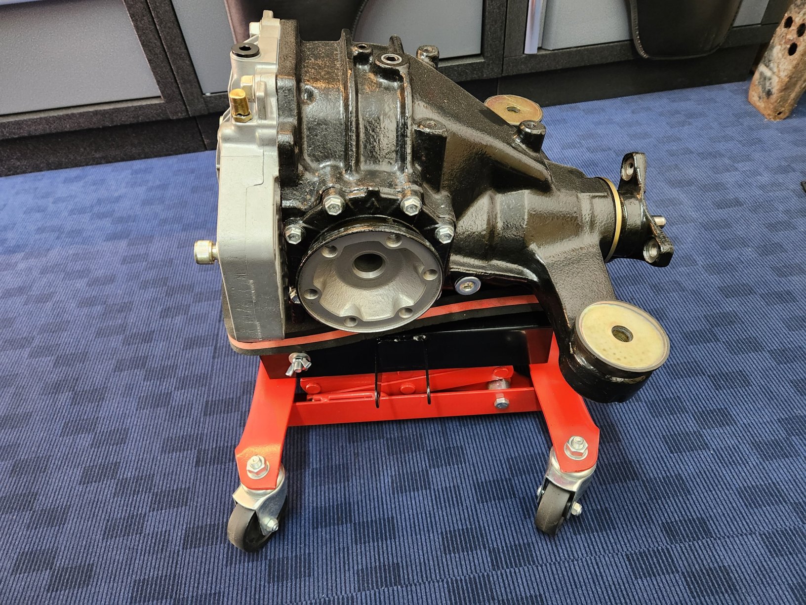
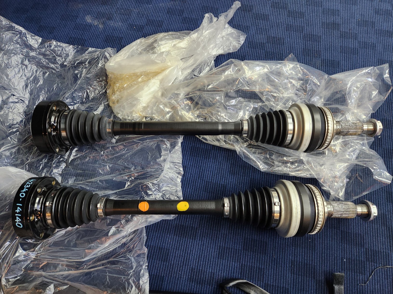
 5 points
 -
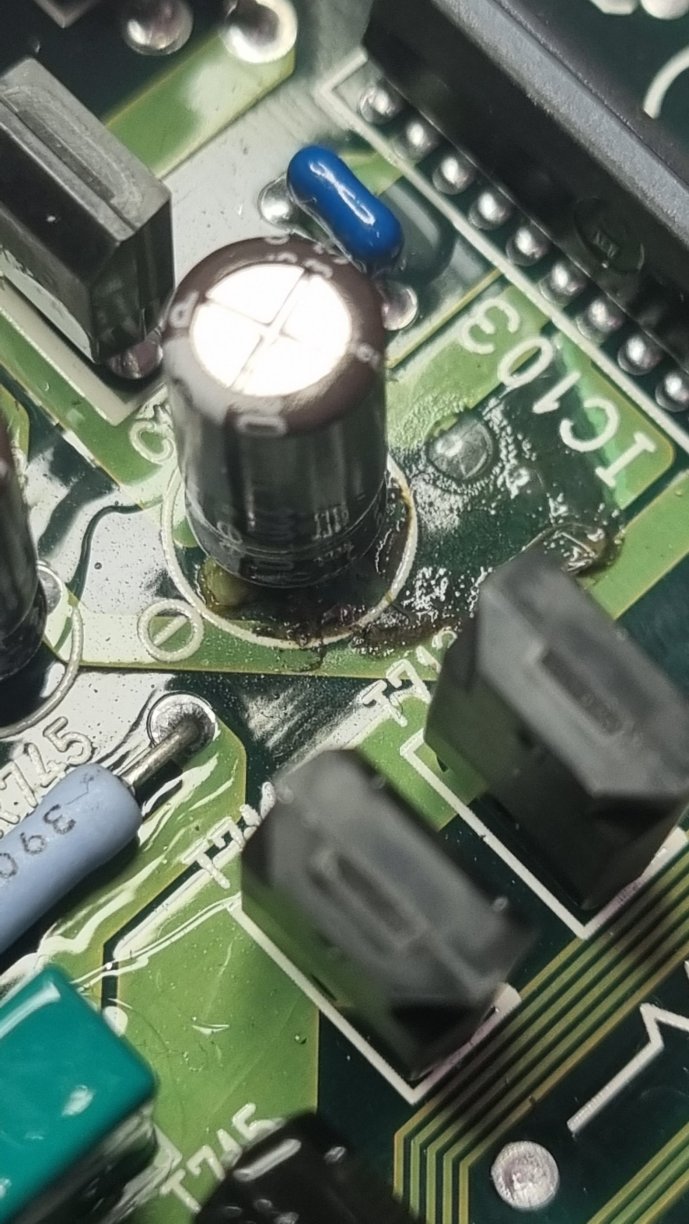
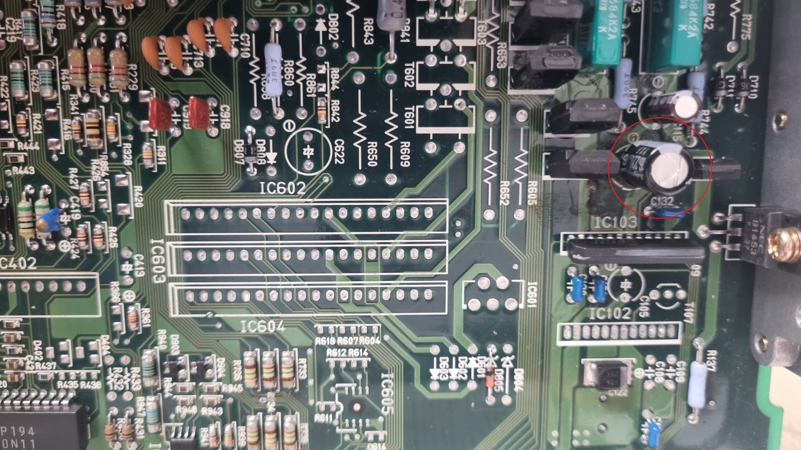
Hi, Not sure if you've solved this but I had a similar idling issue for a long time and finally one day the car just wouldn't start anymore (Jspec TT) after tracing wires for ages from EFI Relays its pointed back to the ECU, turned out a Cap had blown but a different location to your pics, I swapped Cap out and the Car started and and the idling issue went. Could be worth checking this Cap
 3 points
 -
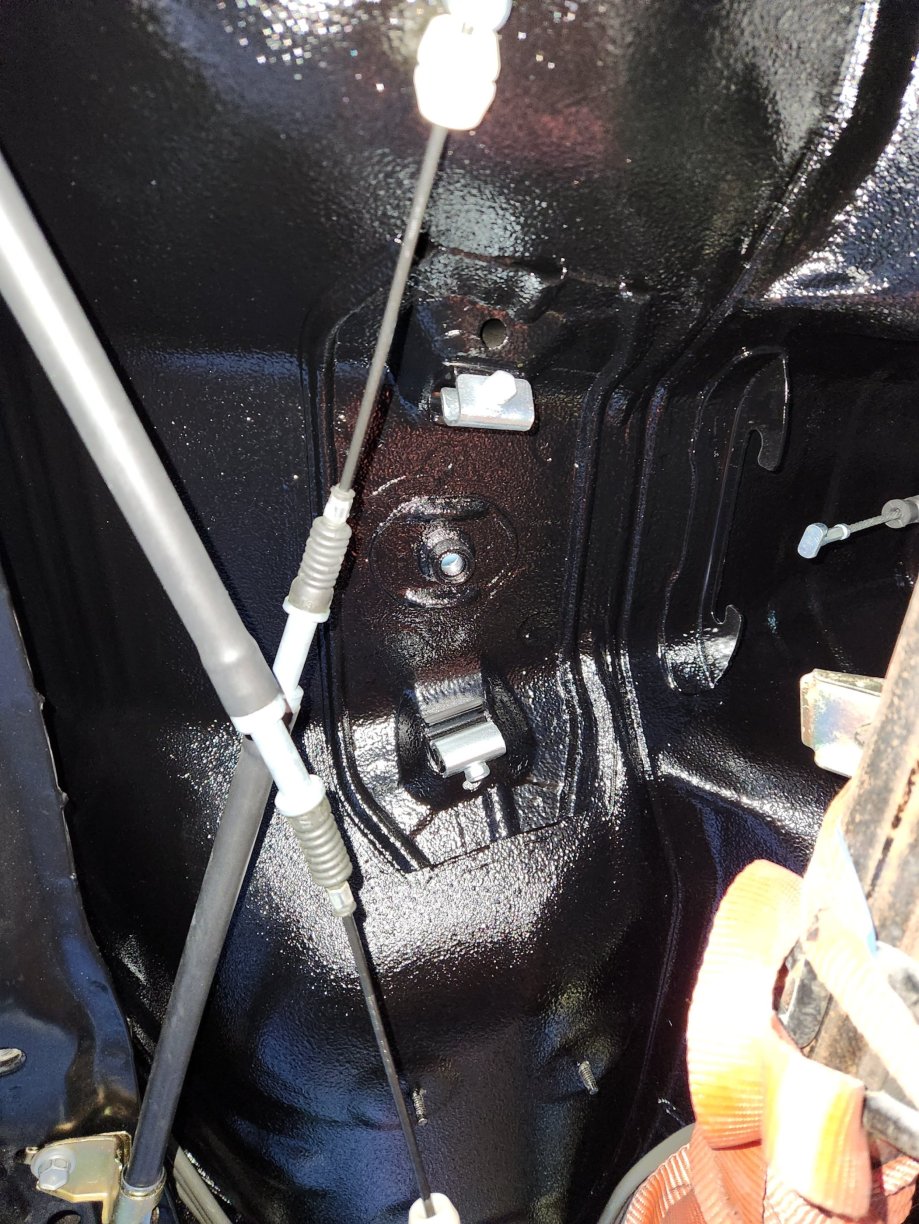
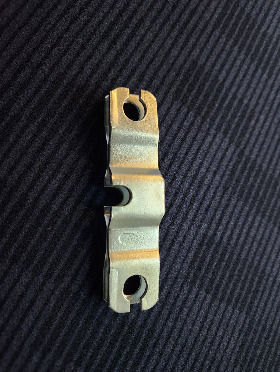
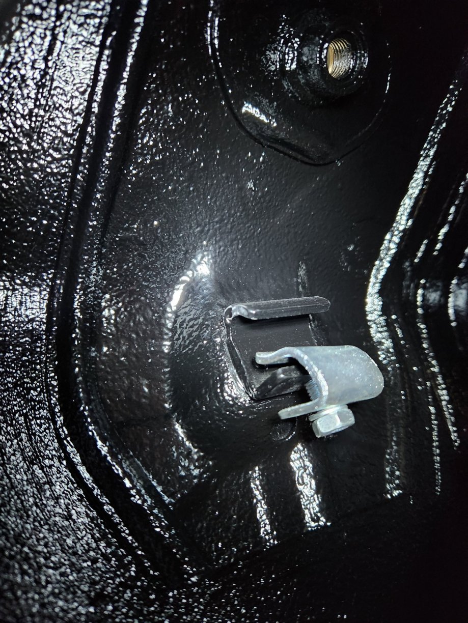
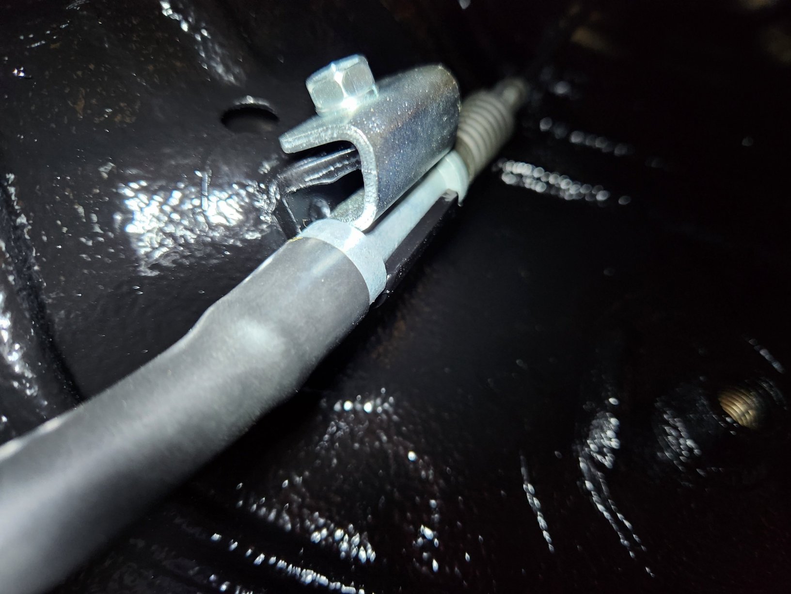
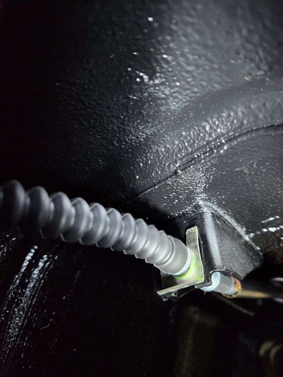
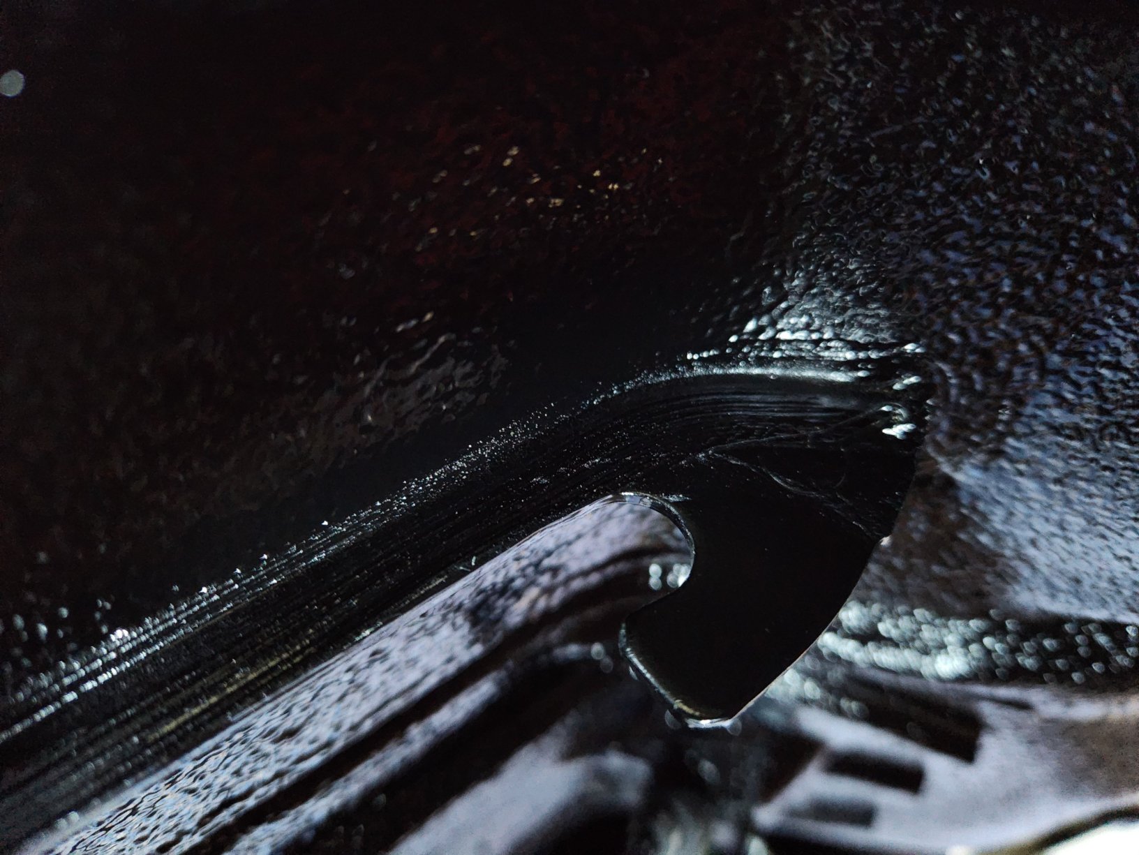
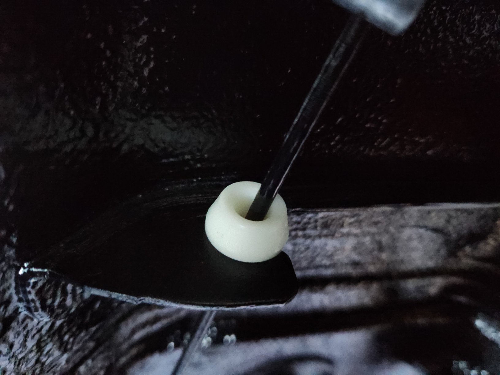
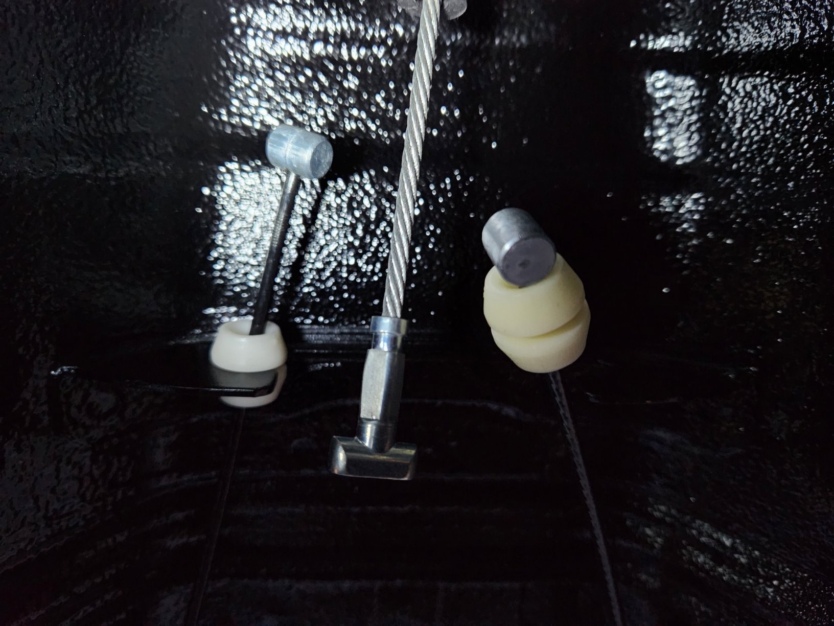
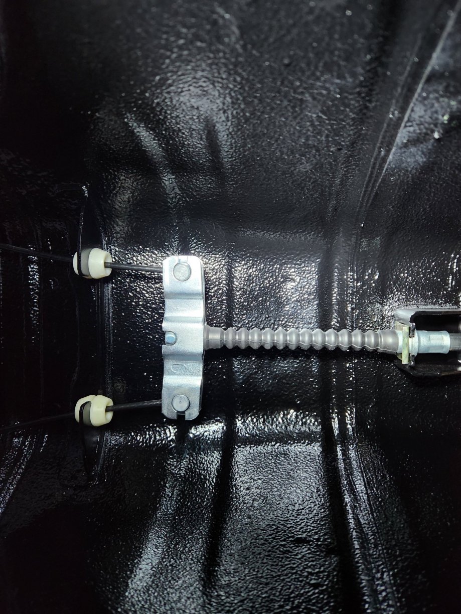
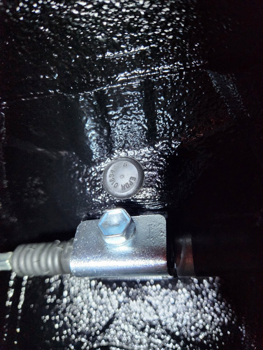
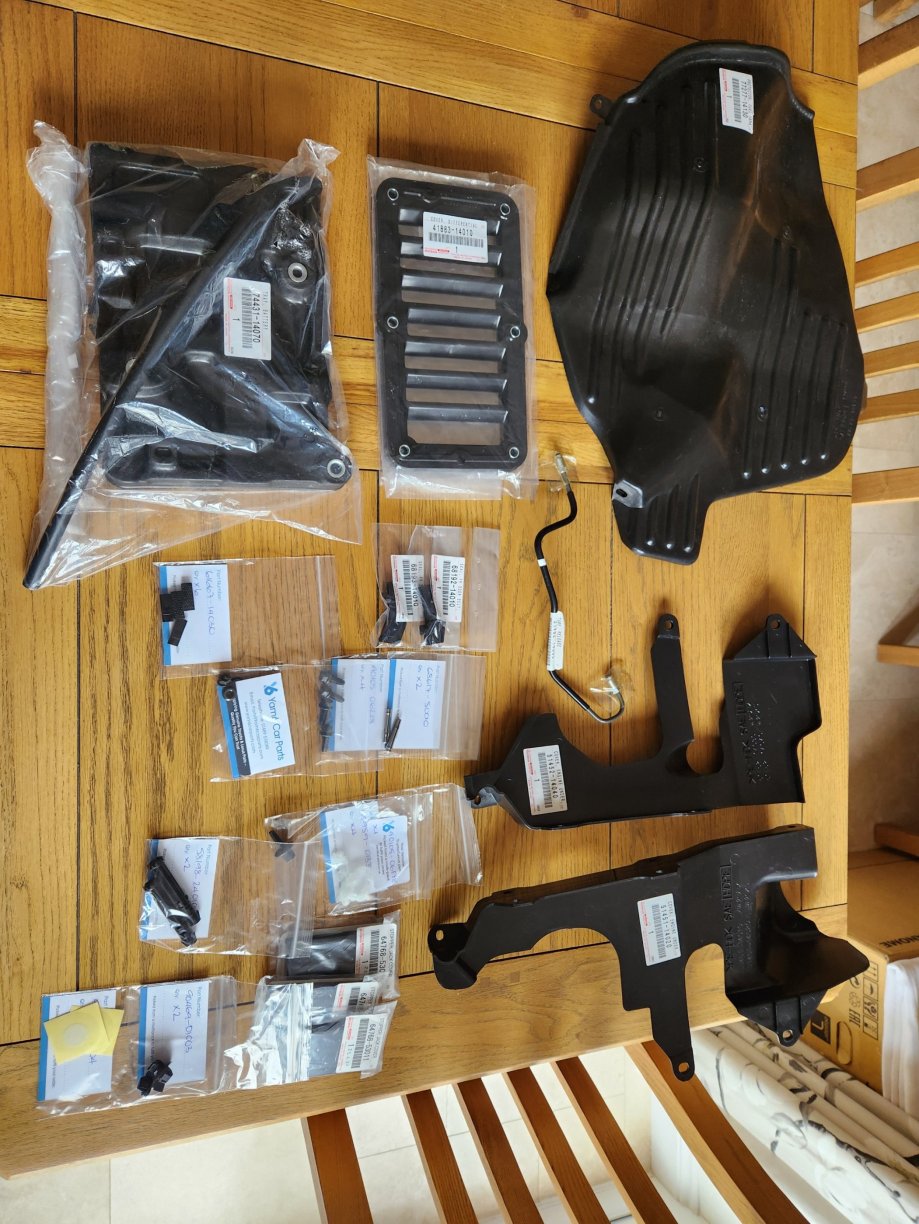
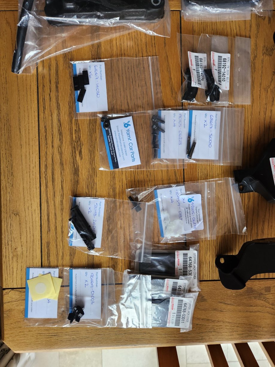
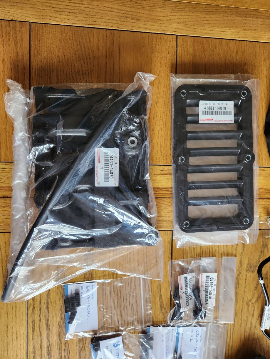
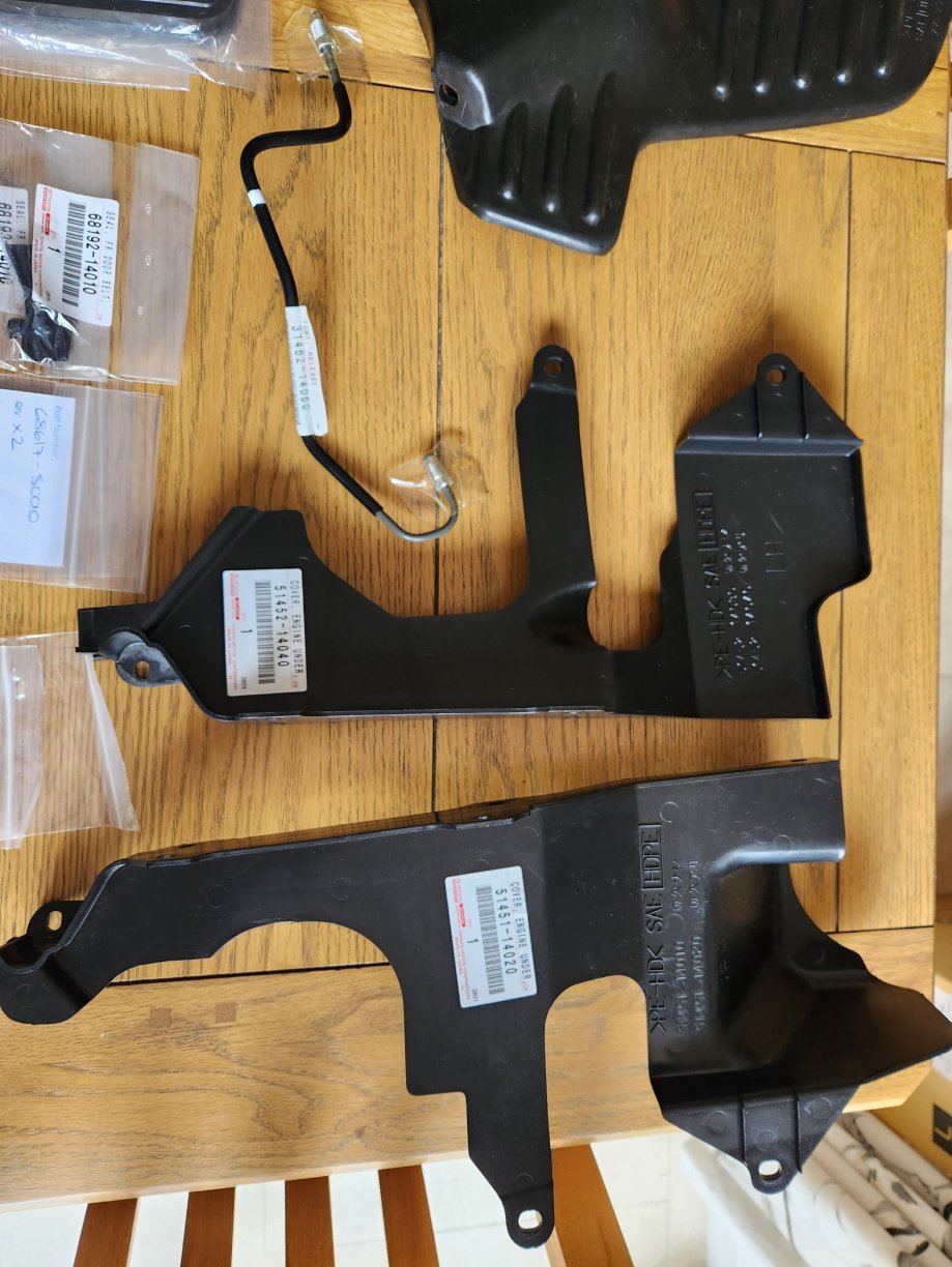
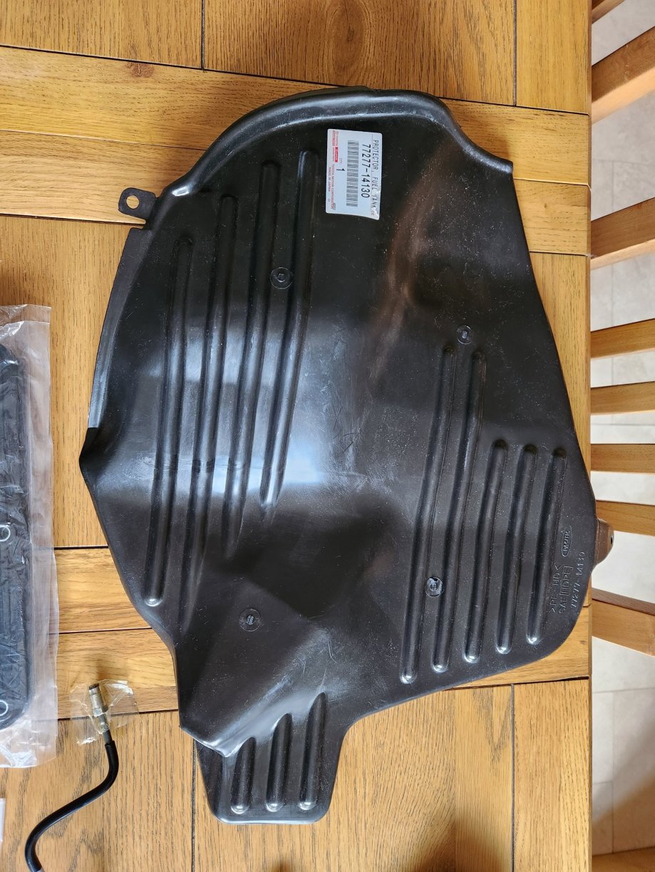
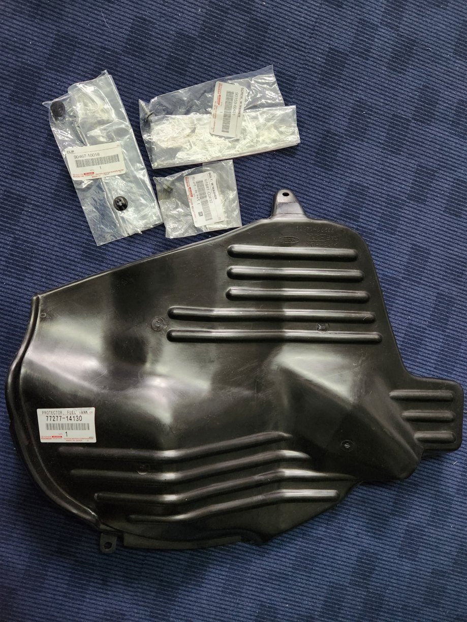
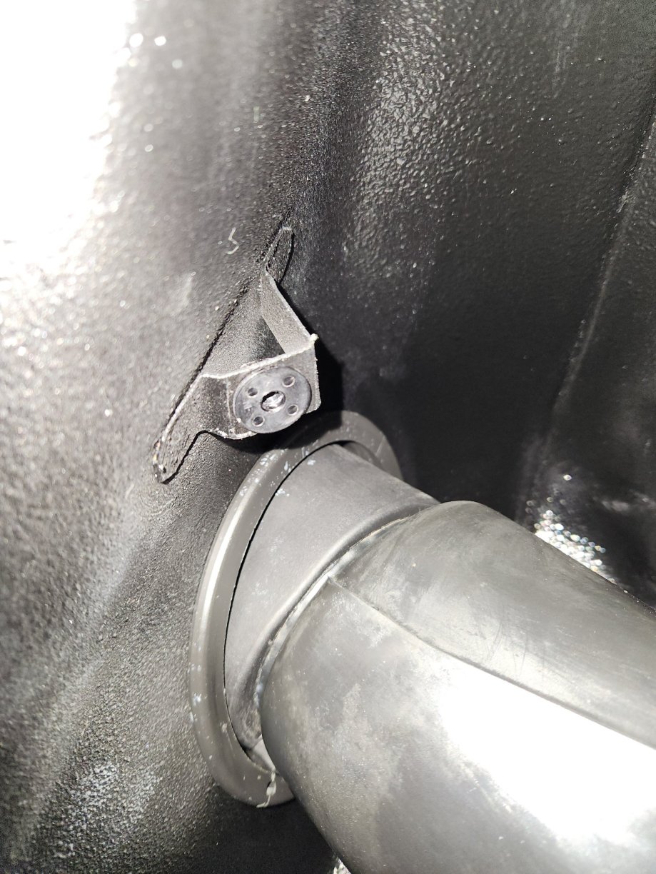
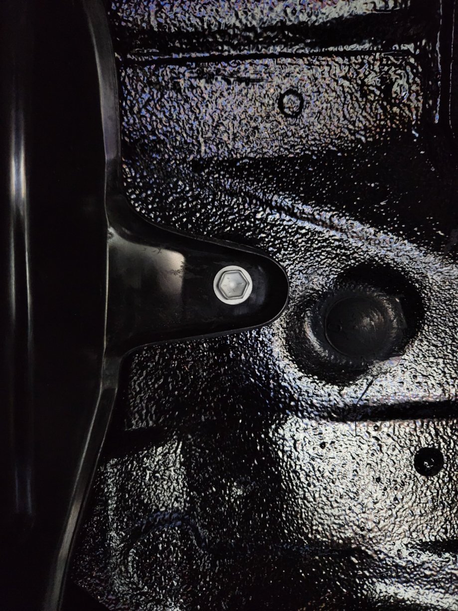
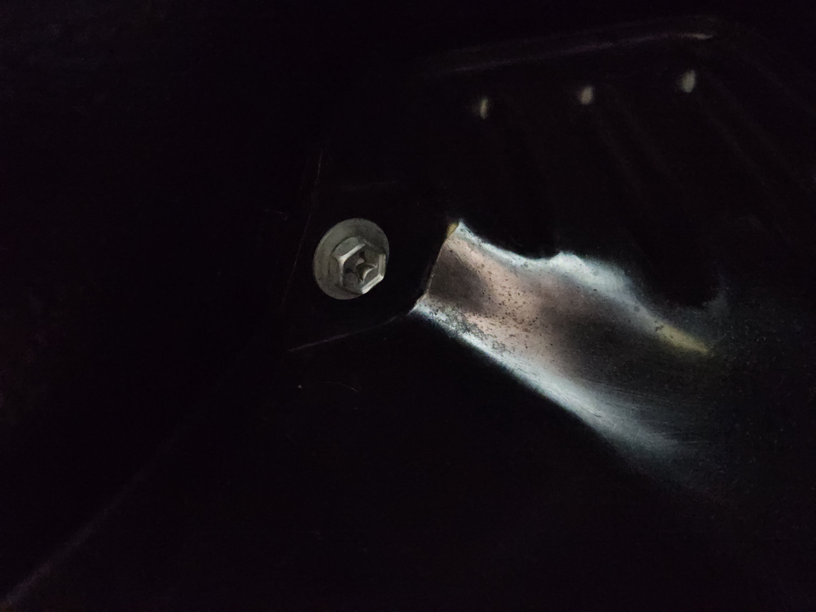
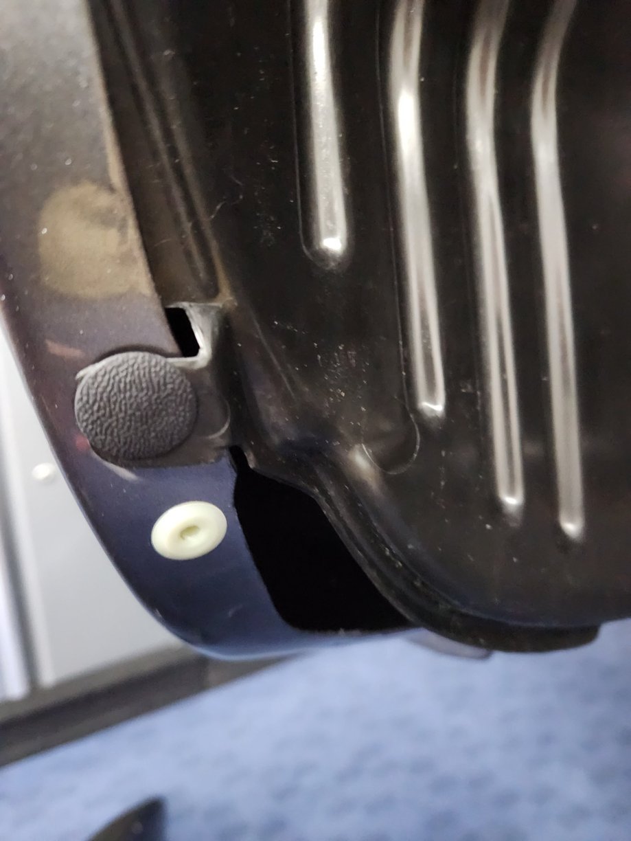
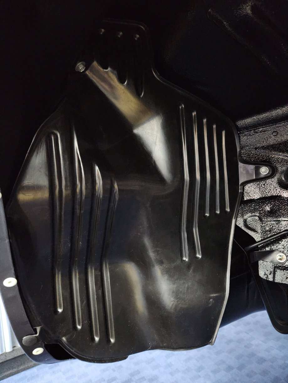
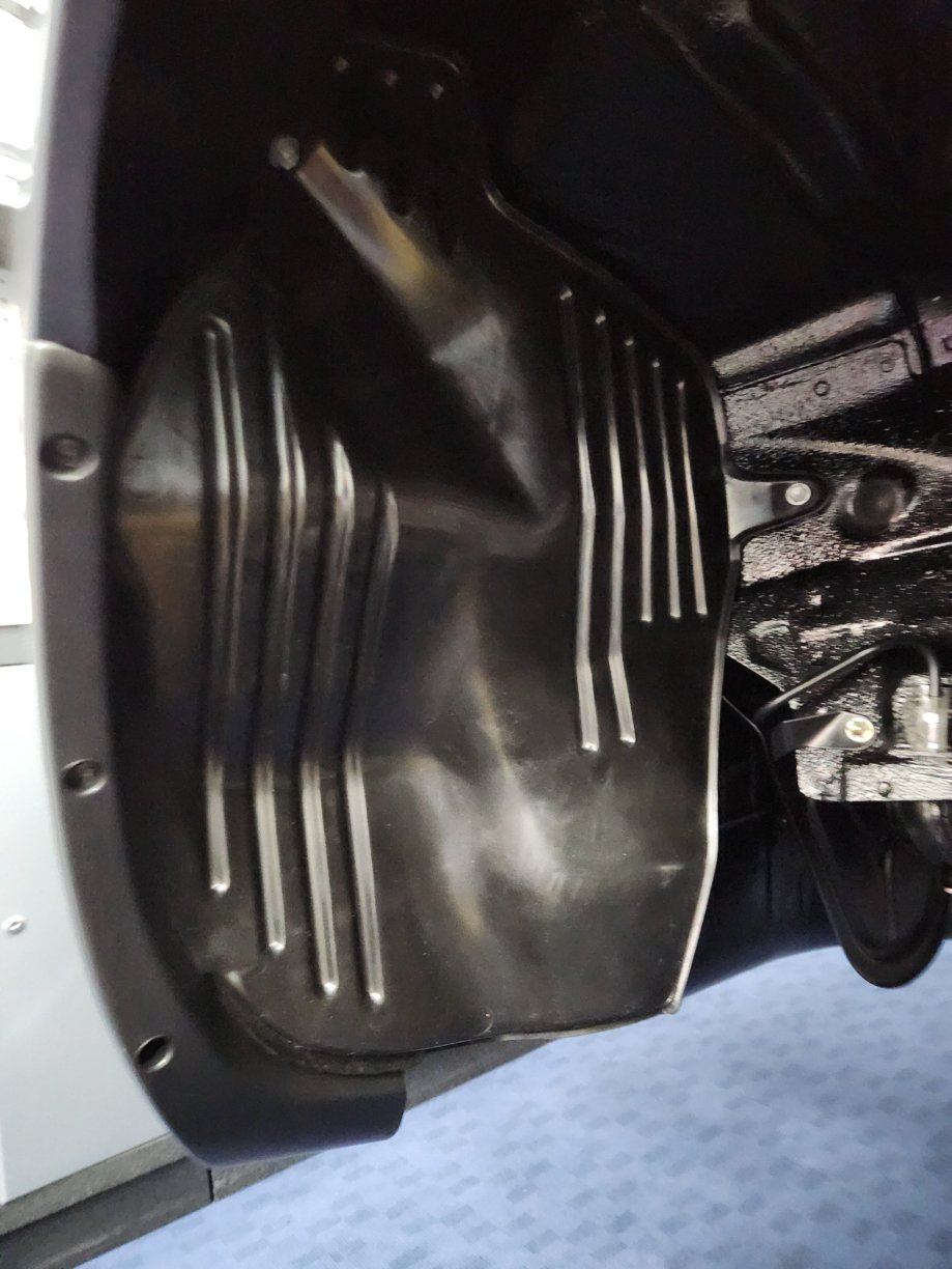
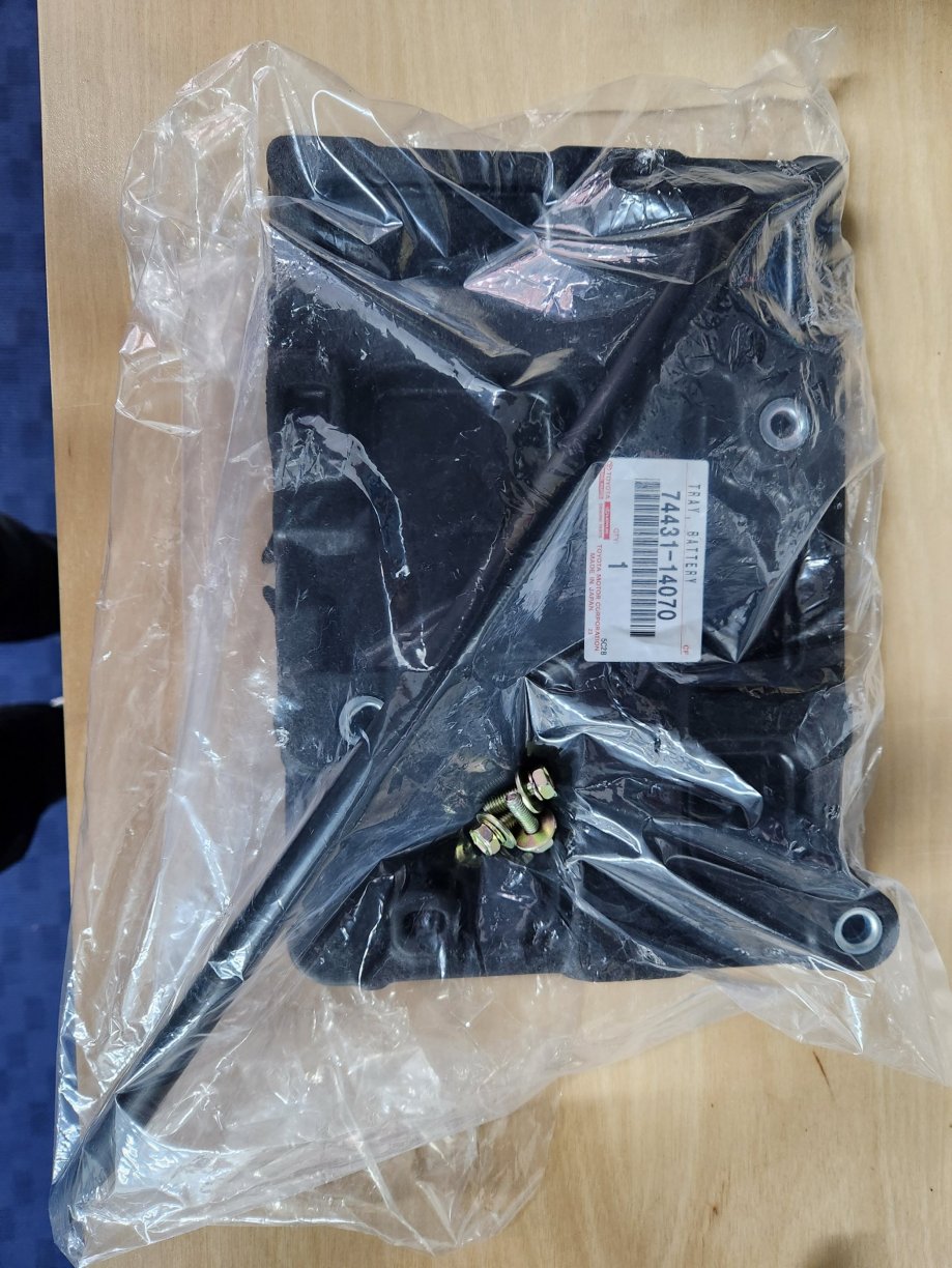
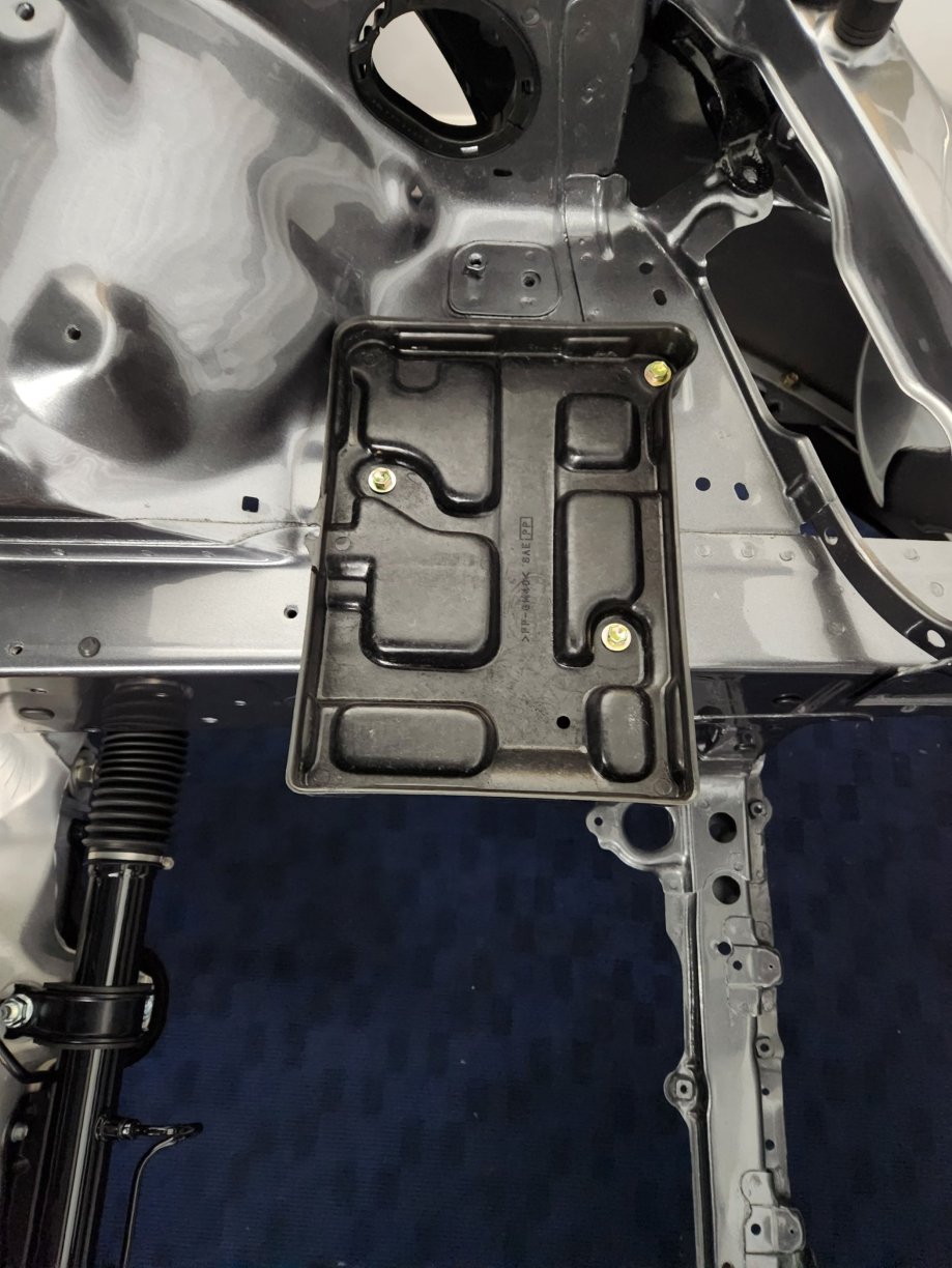
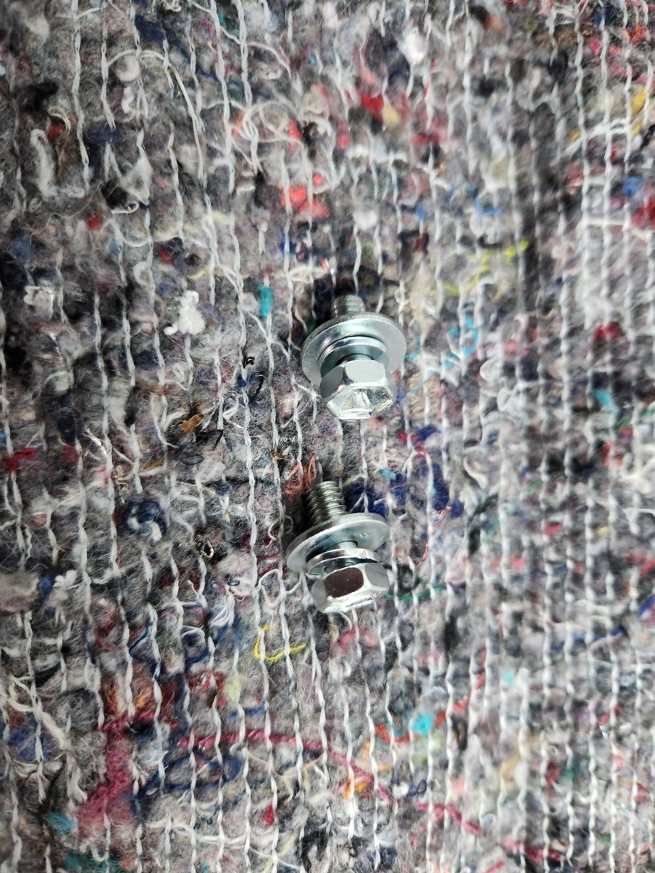
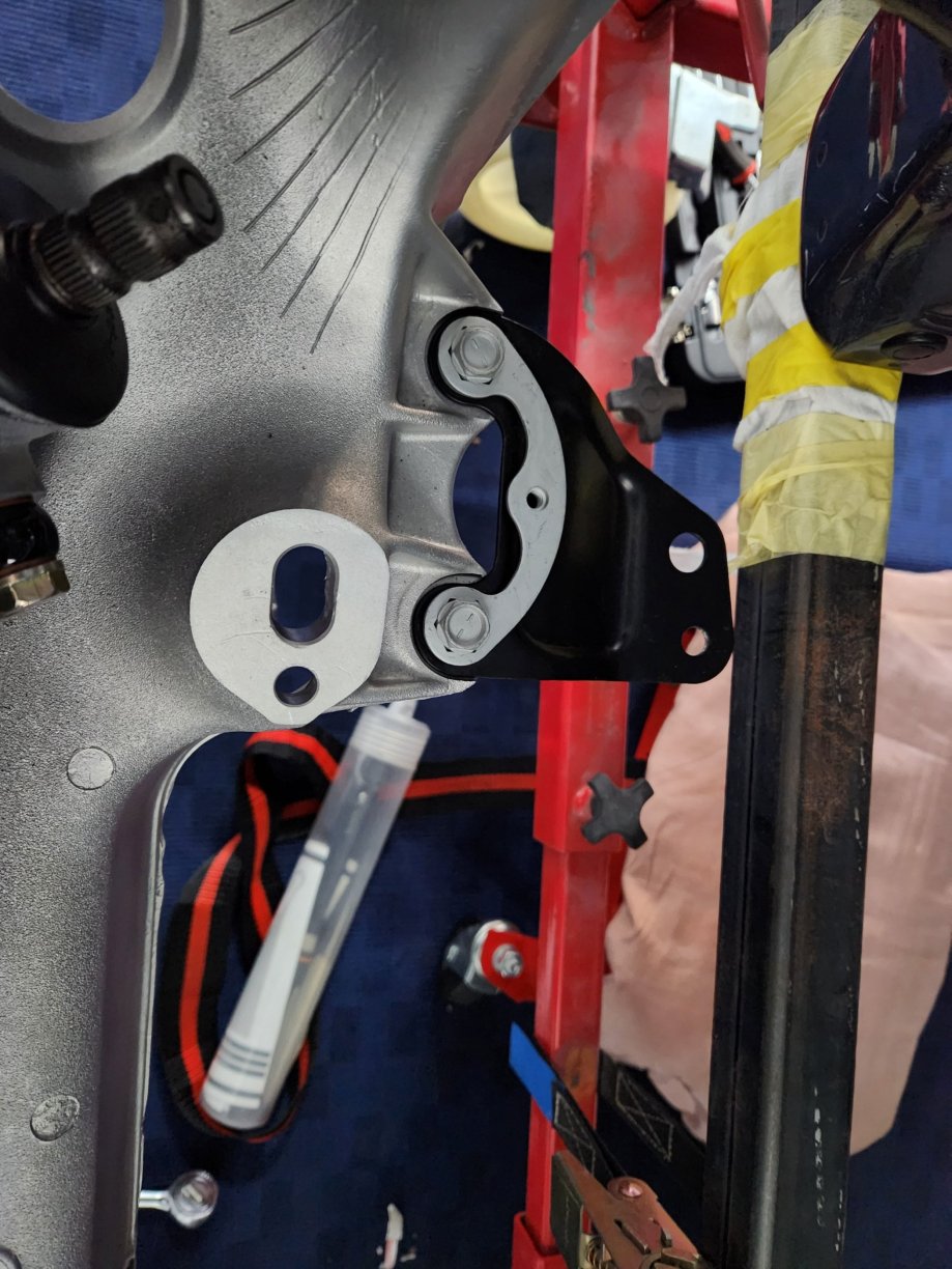
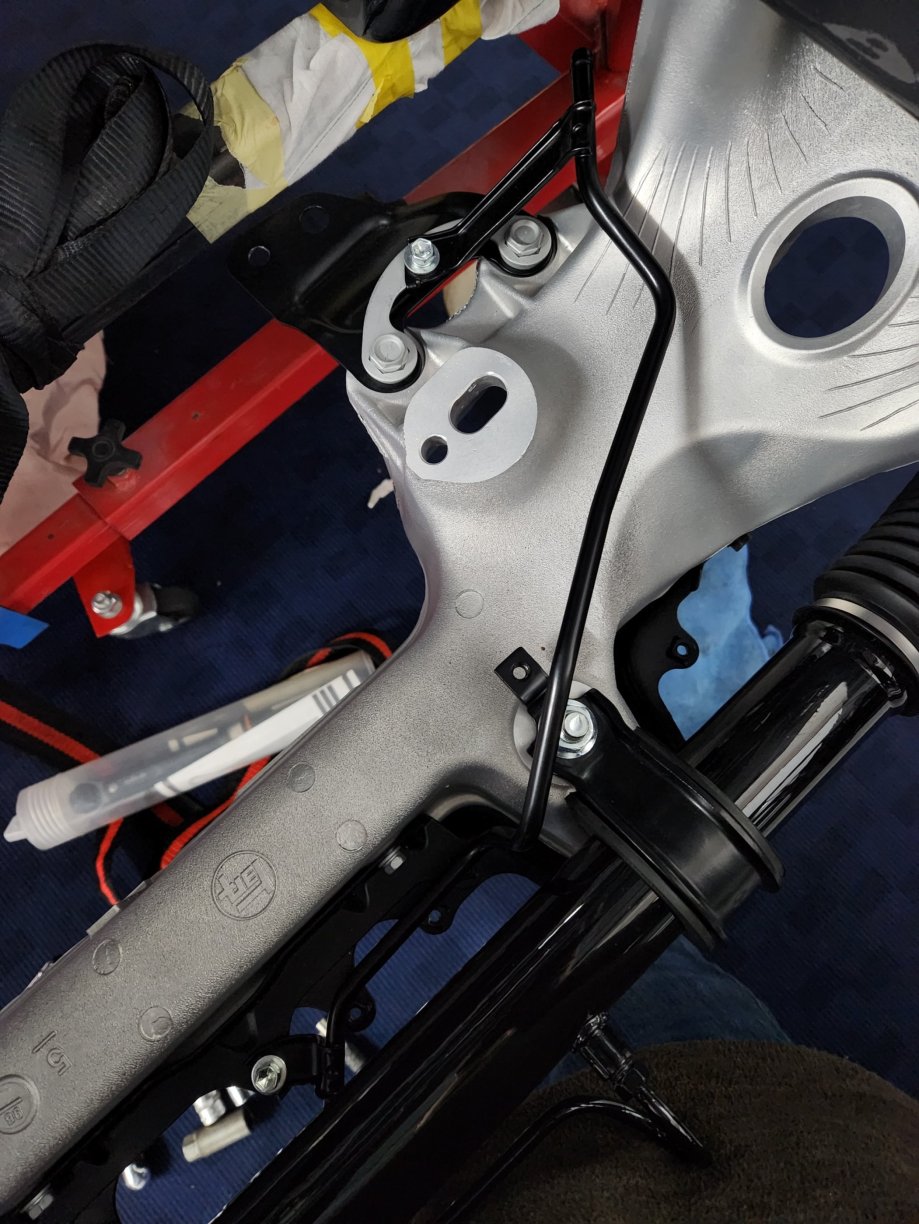
A few small updates. I connected the handbrake cables up. All the cables are new, but I reused the fixings. I also had a small order from Jason at Yam6 come through. I've had to buy another set of theside pod arch grills as the other new set I bought have cracked. I think the new bolts I bought, which were toyota replacement parts for the original bolts, have a slightly larger captive washer. This has placed too much strain on the part and caused them to break. I have previously bought the extended versions of these trim pieces (see below image), but they were longer. These shorter pieces are designed to accommodate the active spoiler setup. I proceeded to fit the rear offside wheel arch protector. All parts were new. Grommet fixes into bracket close to the top of the fuel filler neck. Single bolt installed just above rear brake pipe bracket. Single screw goes into the previously installed grommet. Having removed the hockey sticks, you can push in the plastic retaining clips into the hole in the wing. Finished with hockey stick reinstalled. I also installed the new battery tray. I used three of my plated bolts instead of the new ones I bought.
 3 points
 -
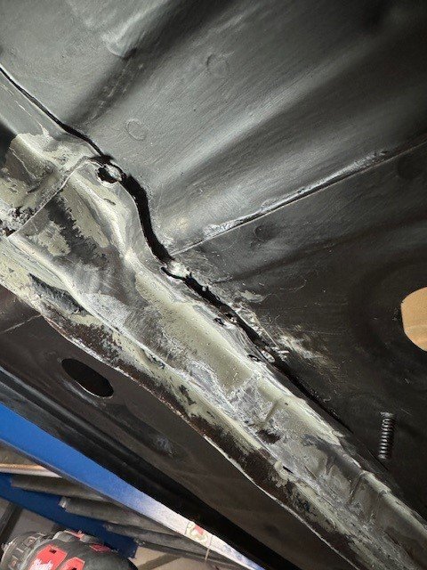
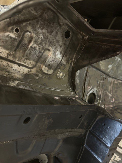
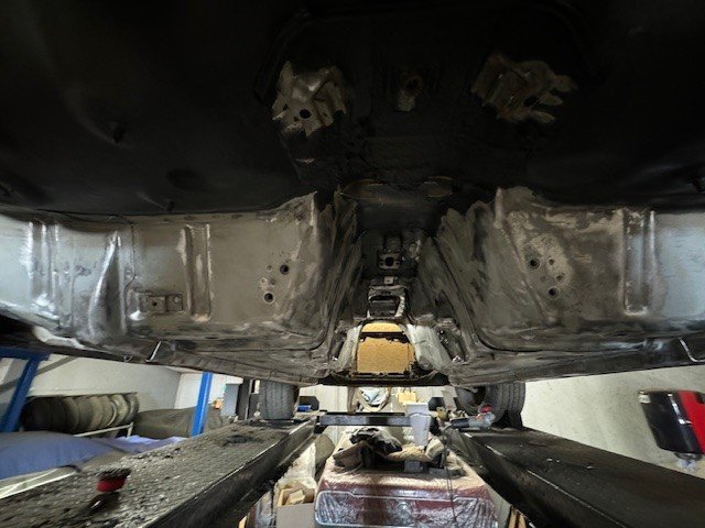
Took a half day off yesterday to try get some more bits done. The box section had been crushed at some point. No idea how - my best guess is maybe the previous owner reverse over a bike or something.. So ended up drilling the spot welds to get the 2 pieces out so that they can be repaired/replaced. Scotched up the rear section ready for seam sealing. I need to make a start on cleaning the unit up though as it's not in a good way after this project Making a start on disassembling the rear subframe today
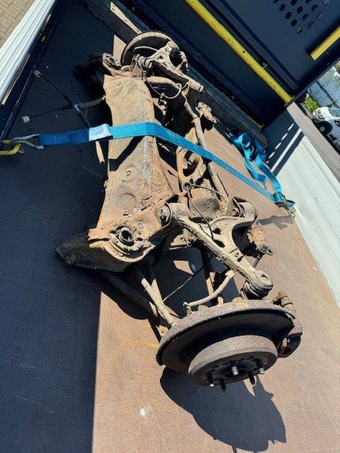
 3 points
 -
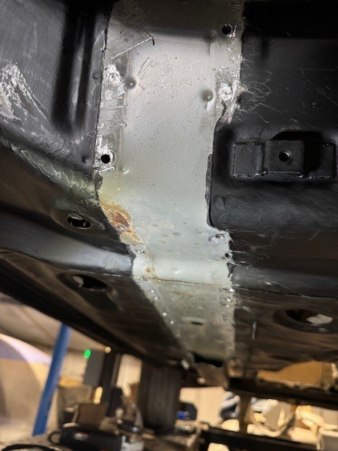
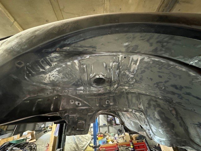
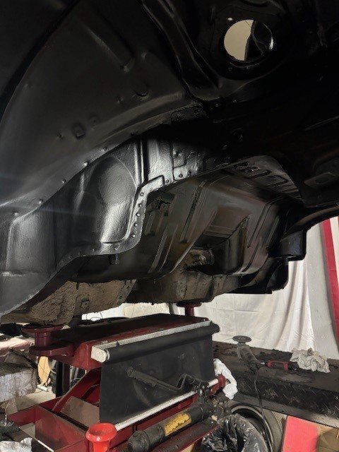
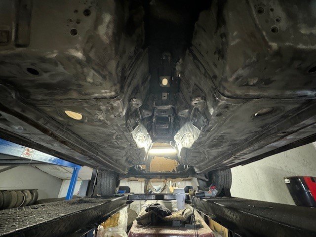
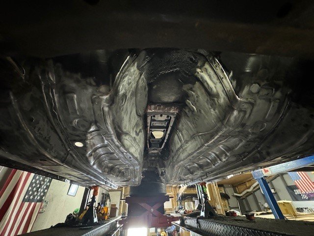
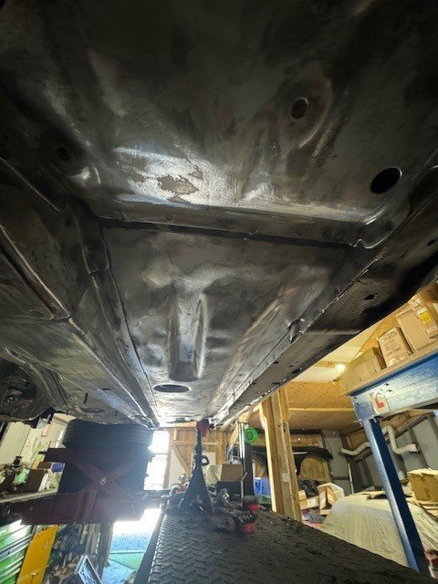
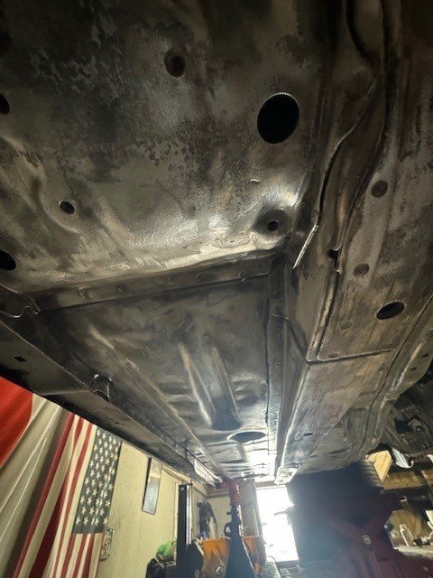
Forgot i hadn't updated this in a while Wheel well and all surrounded areas are painted in 2k epoxy. As is the wheel arches. I have now rubbed down the whole centre section and floor pans and have painted them (pics later) Next plan is to grey scotch all the paint, apply seam sealer then apply Dinitrol 447 to the underbody. It's a stoneguard that has Zinc within it for added protection.
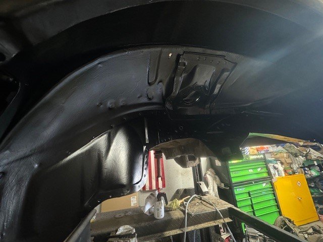
 3 points
 -
I actually made a YouTube channel which will have the supra build on it plus any updates etc, feel free to check it out. https://youtube.com/@kylemillward2 points
-
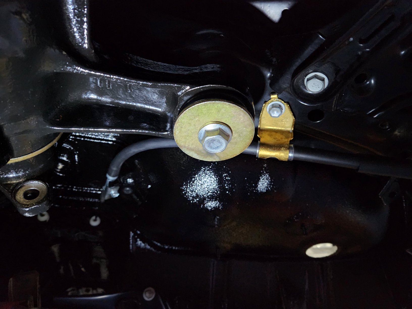
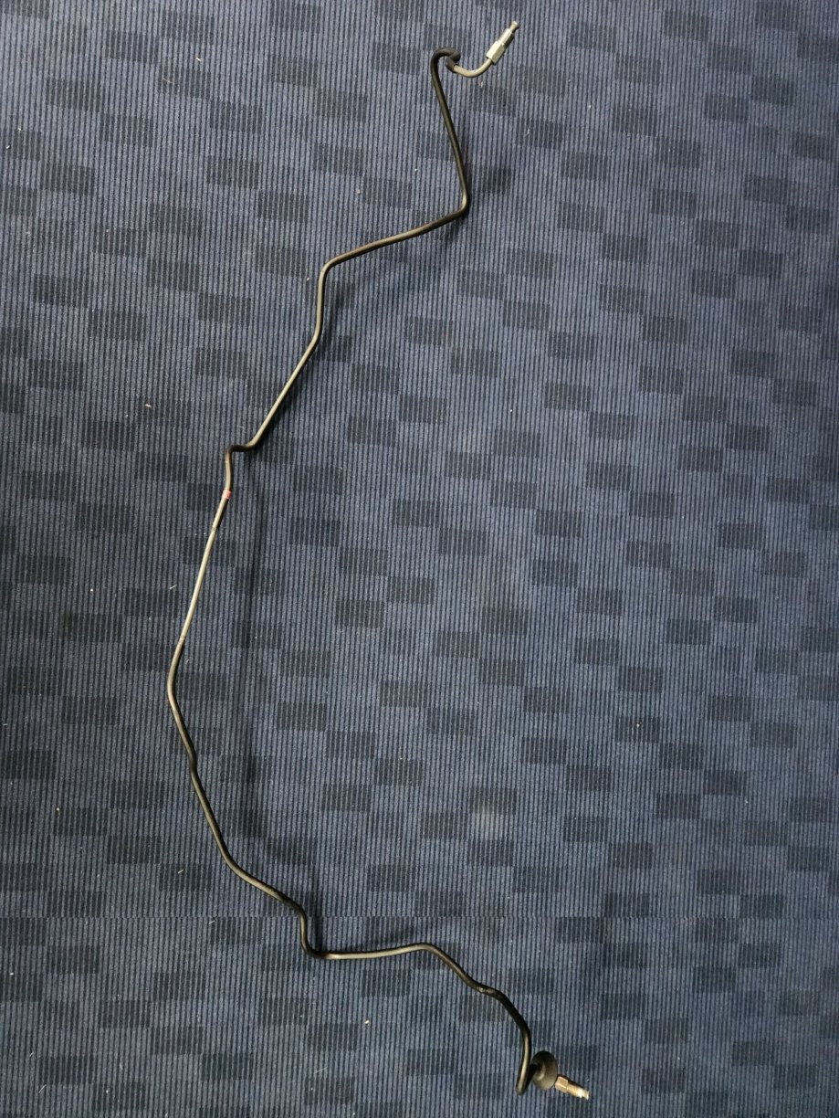
Make sure you don't mess up that front off side OEM brake pipe. It's discontinued. It was the only brake pipe I couldn't get new If you buy one of these: https://www.amazon.co.uk/gp/aw/d/B000KJKJ98?psc=1&ref=ppx_pop_mob_b_asin_title You can dot mark the bolts you've torqued up. This is what I'm doing.2 points
-
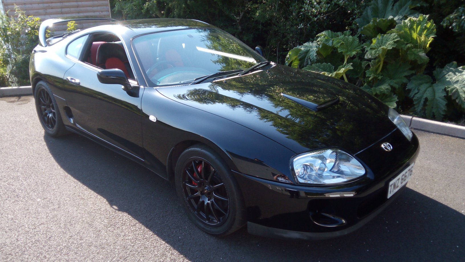
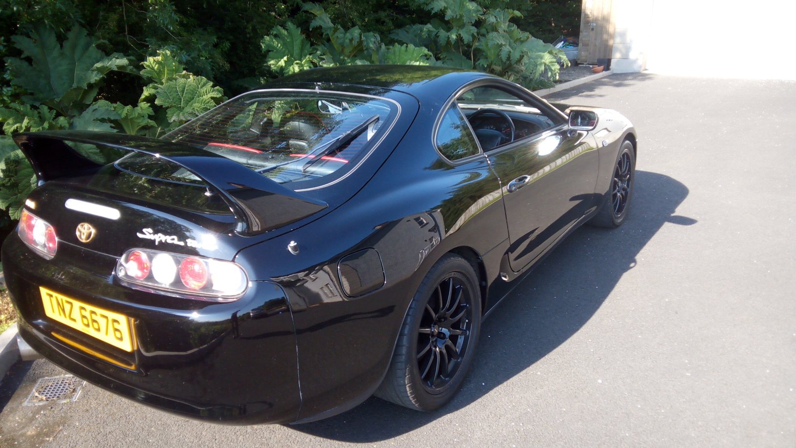
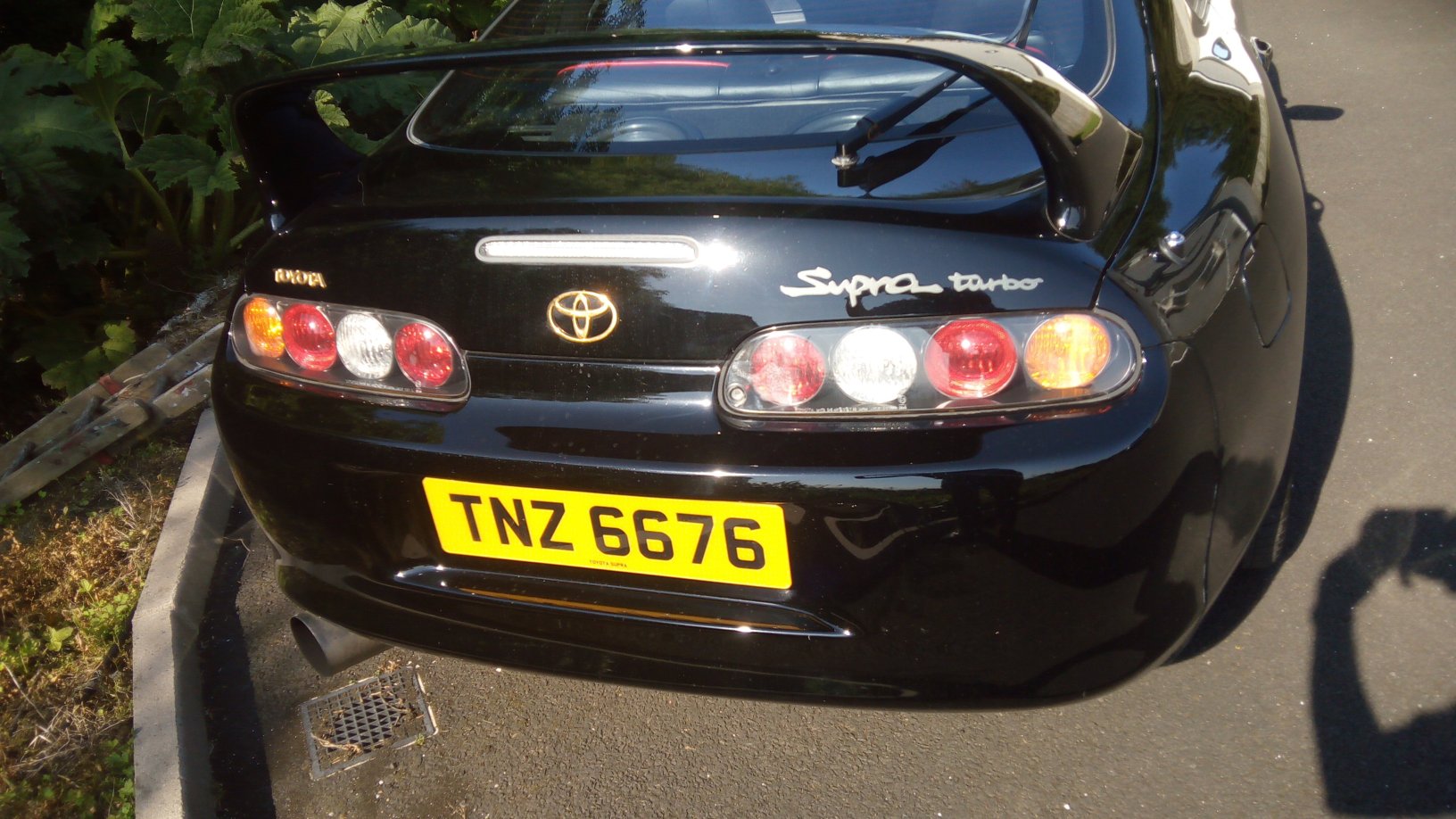
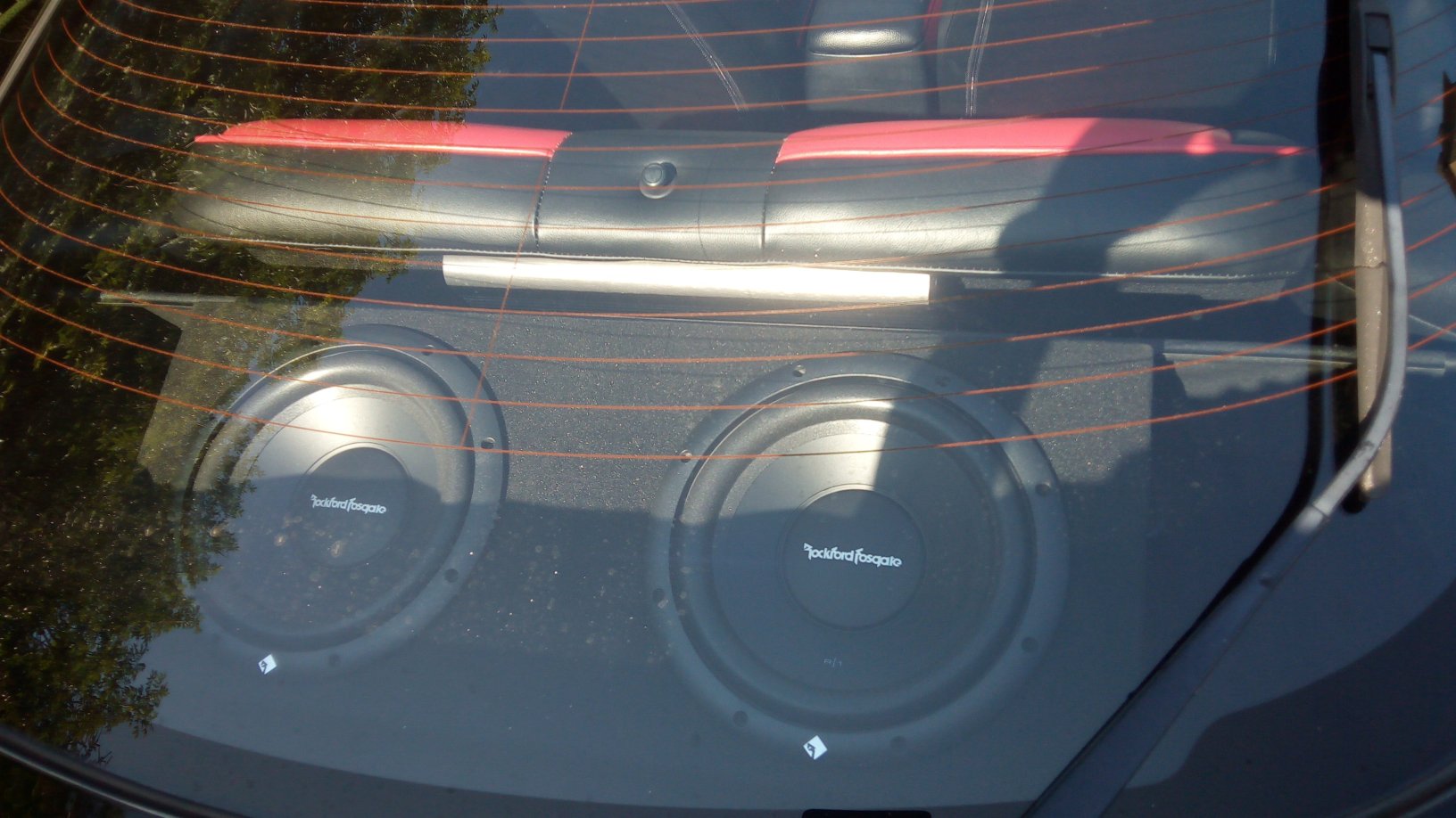
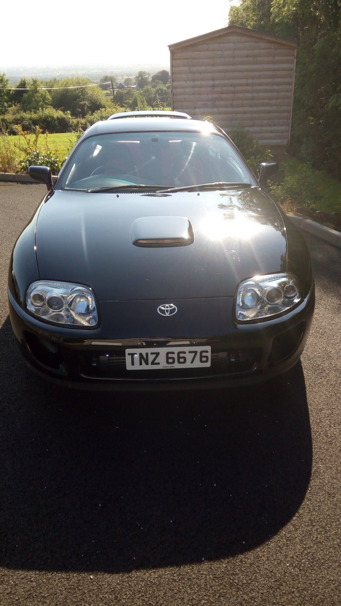
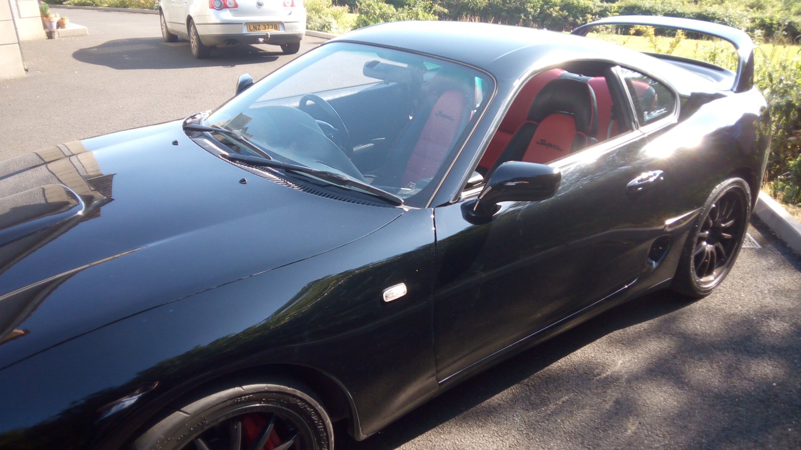
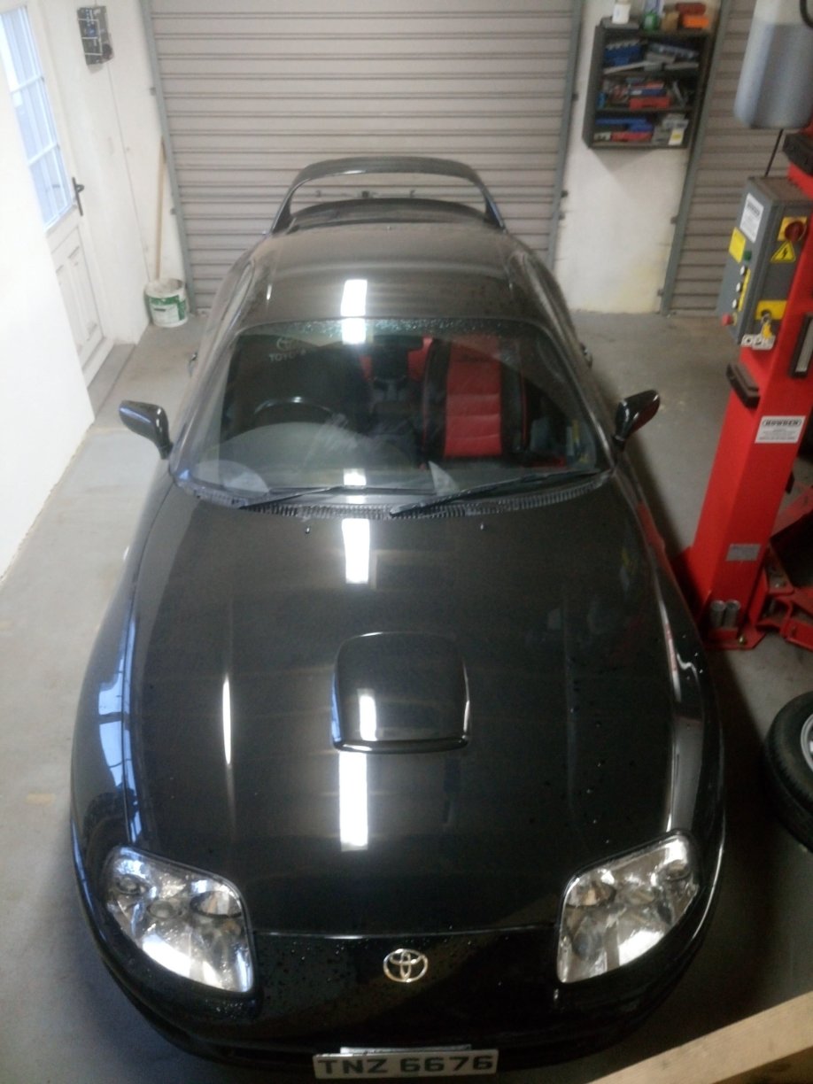
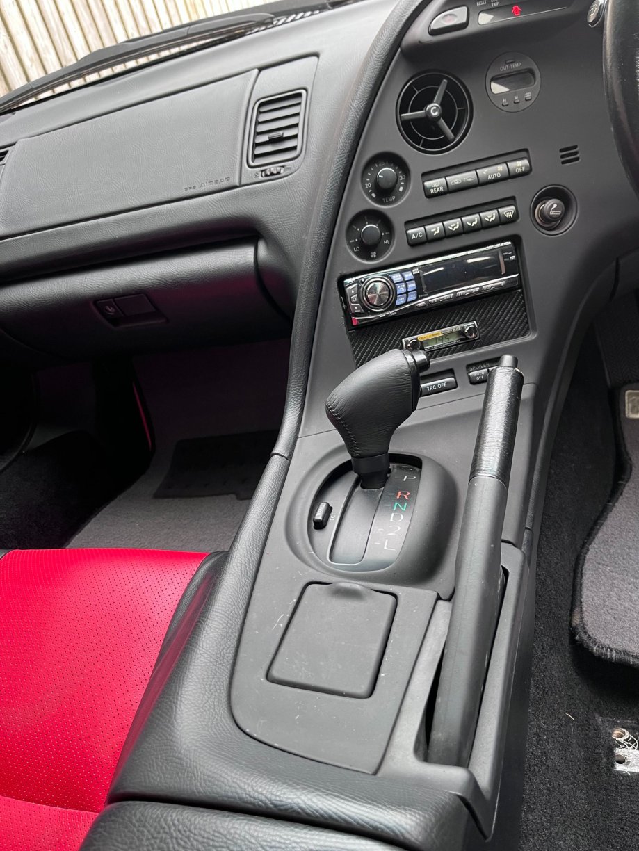
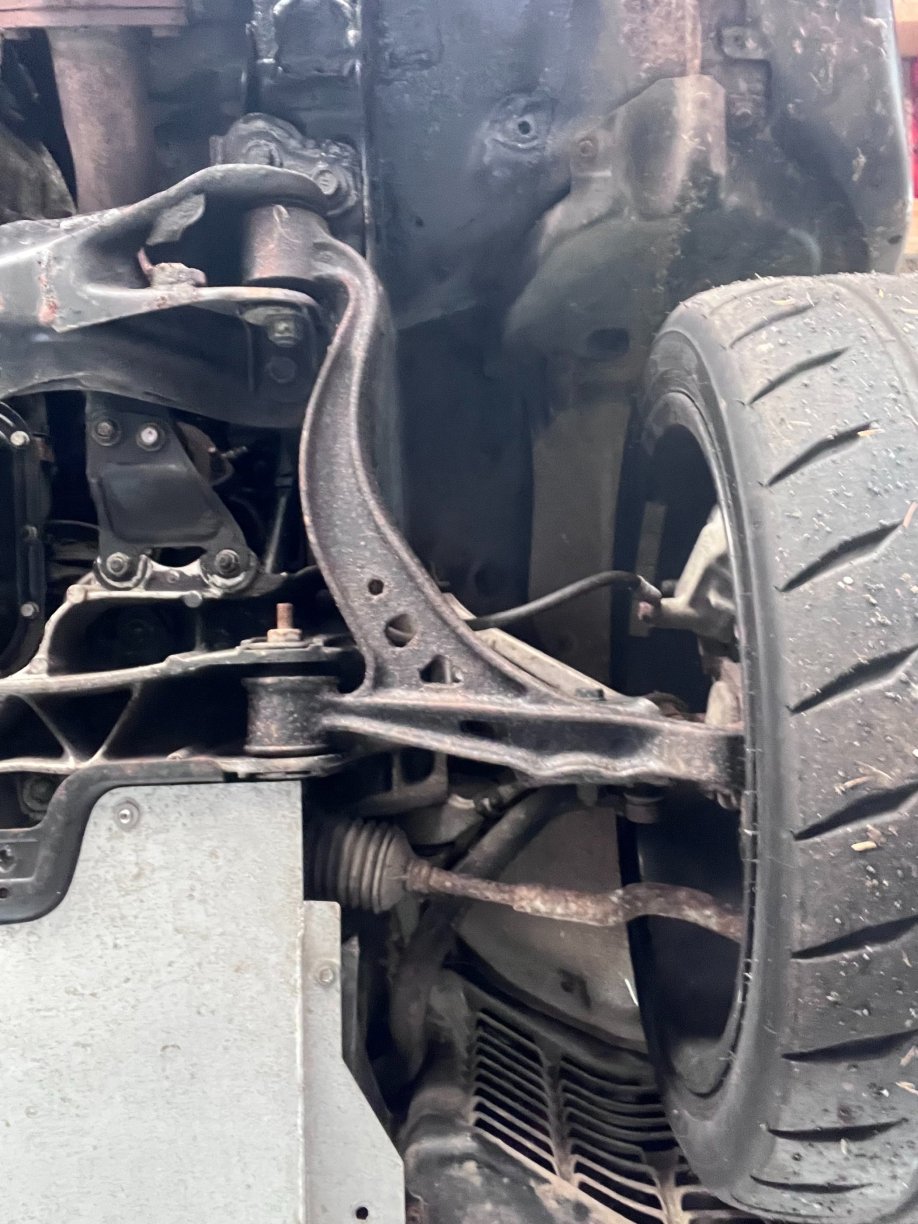
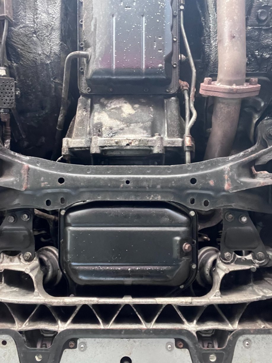
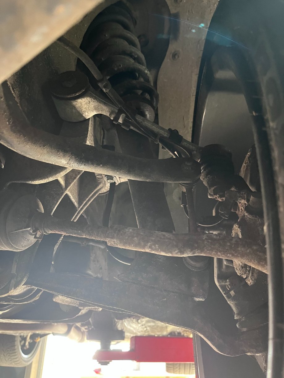
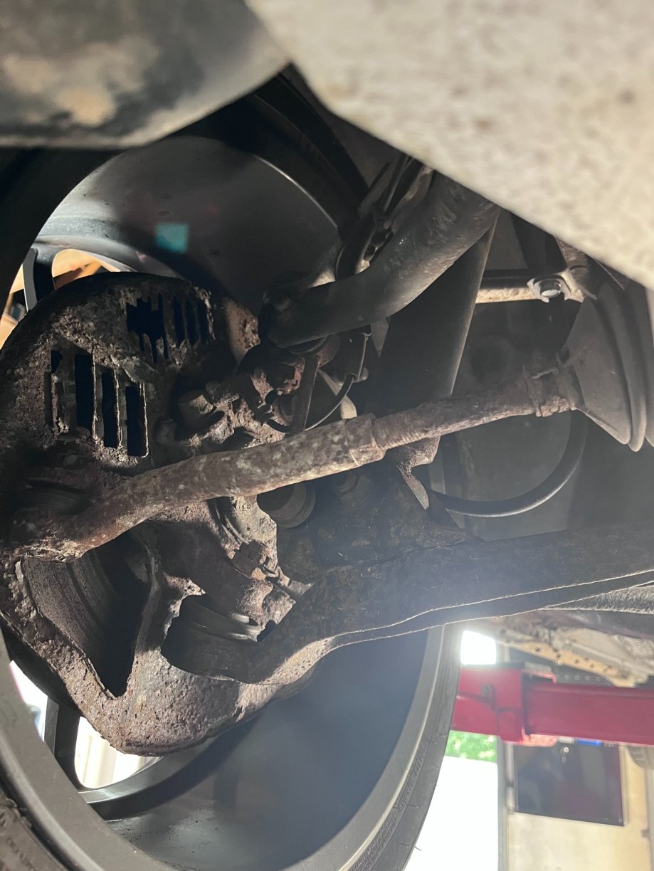
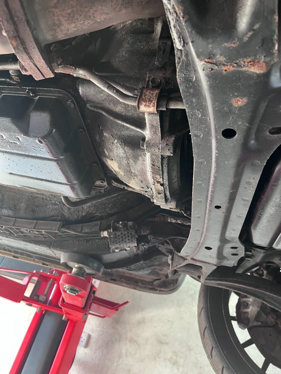
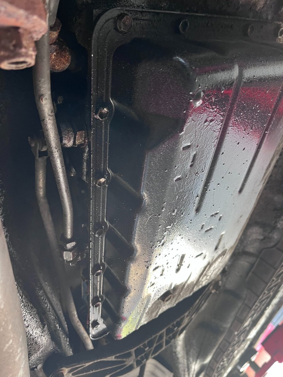
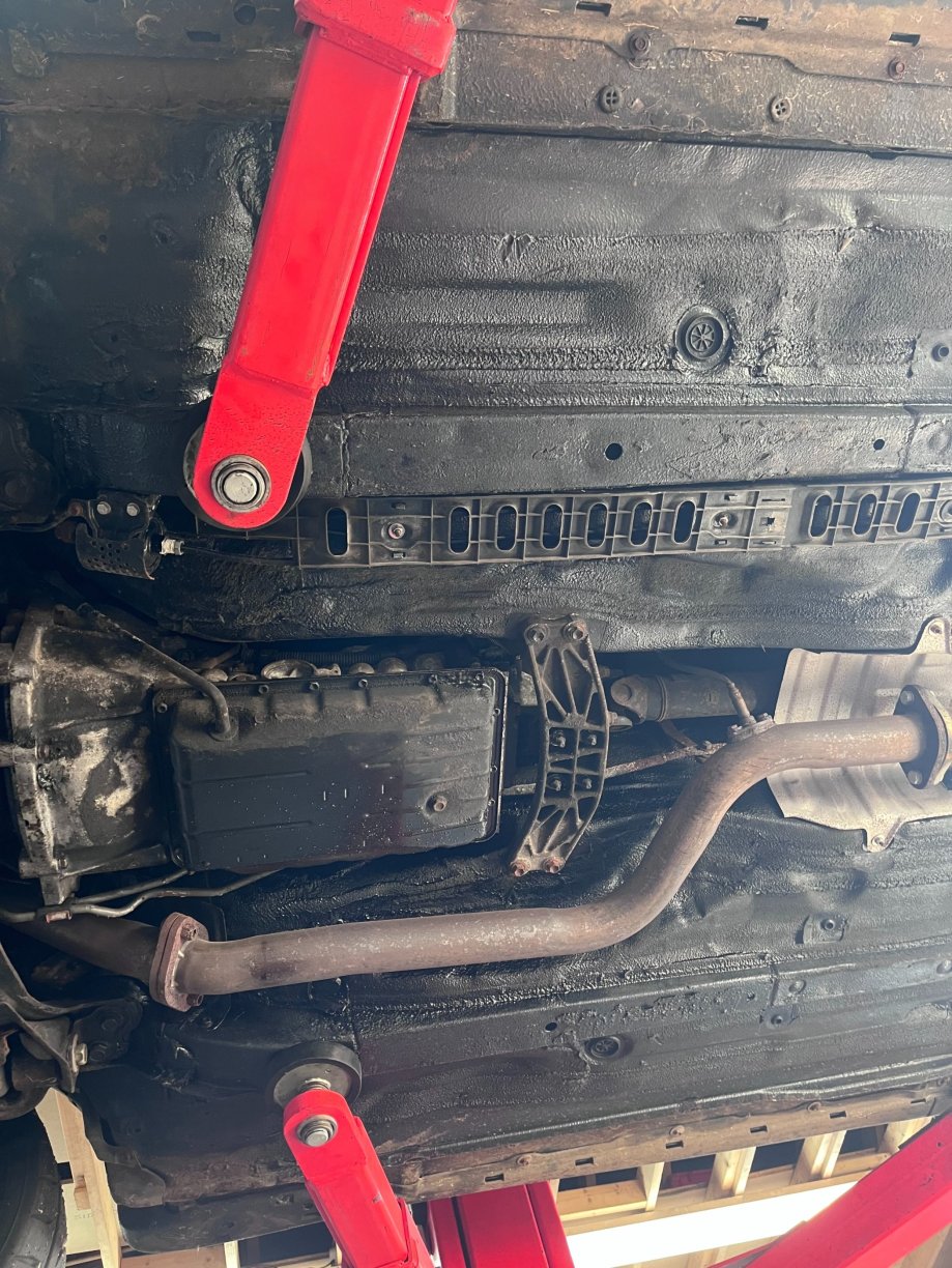
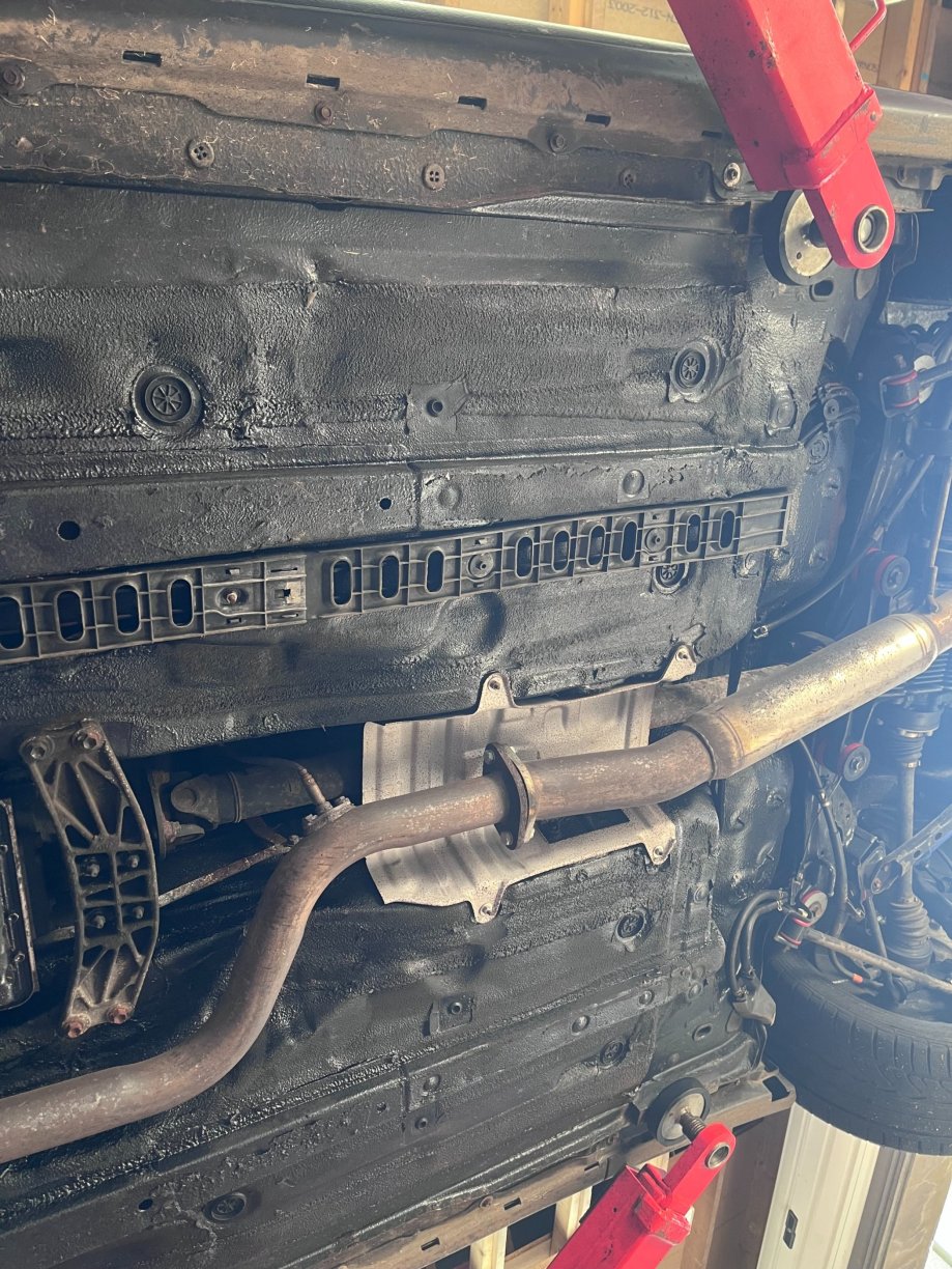
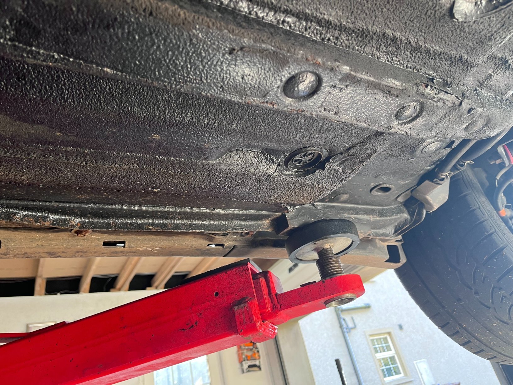
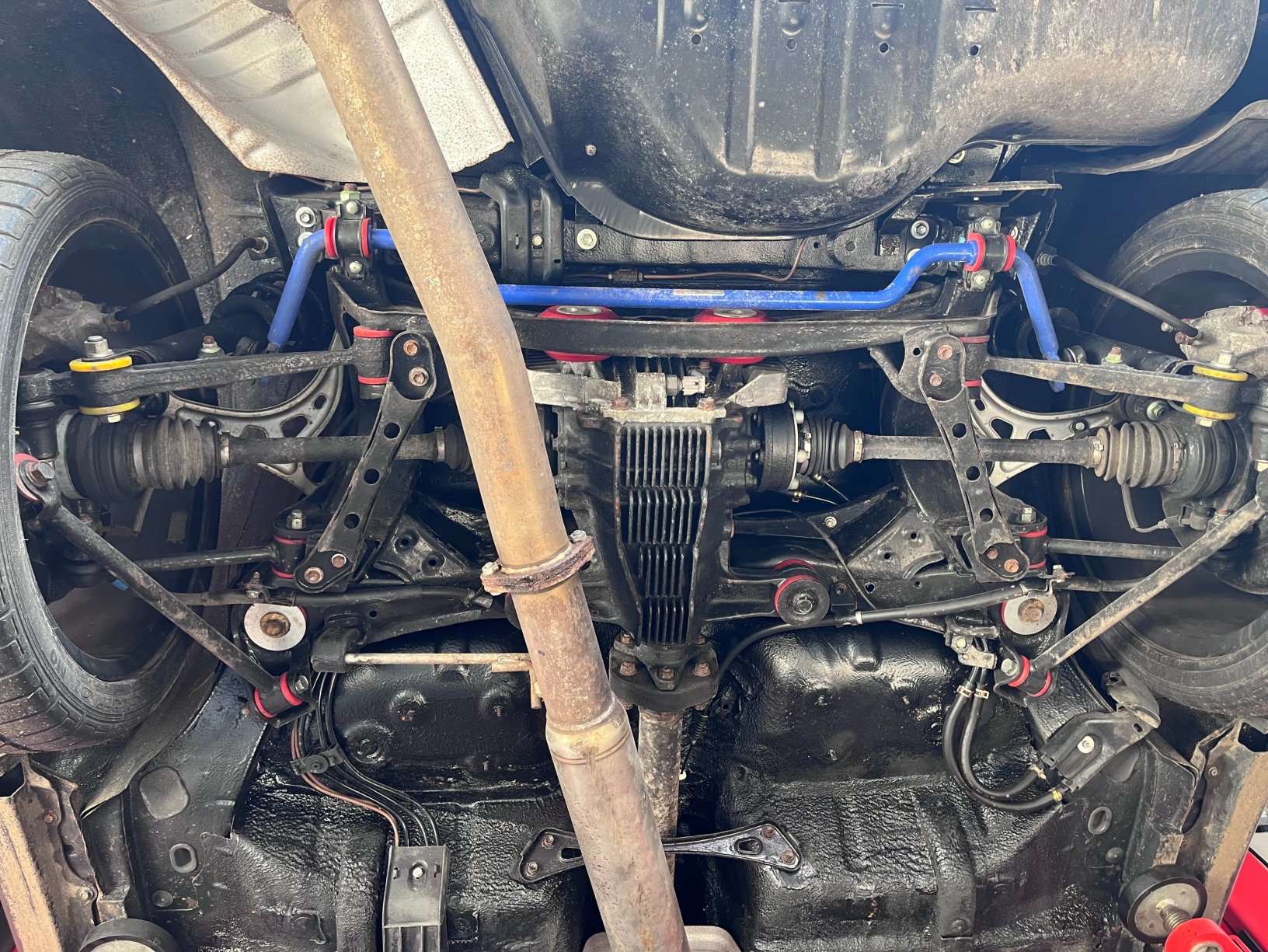
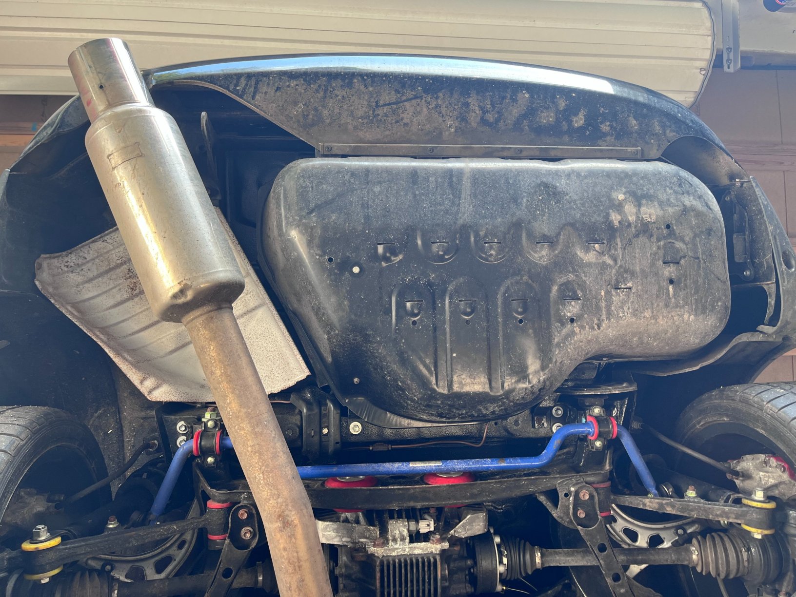
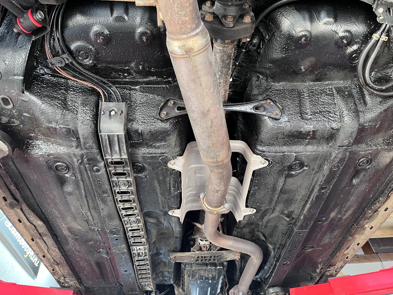
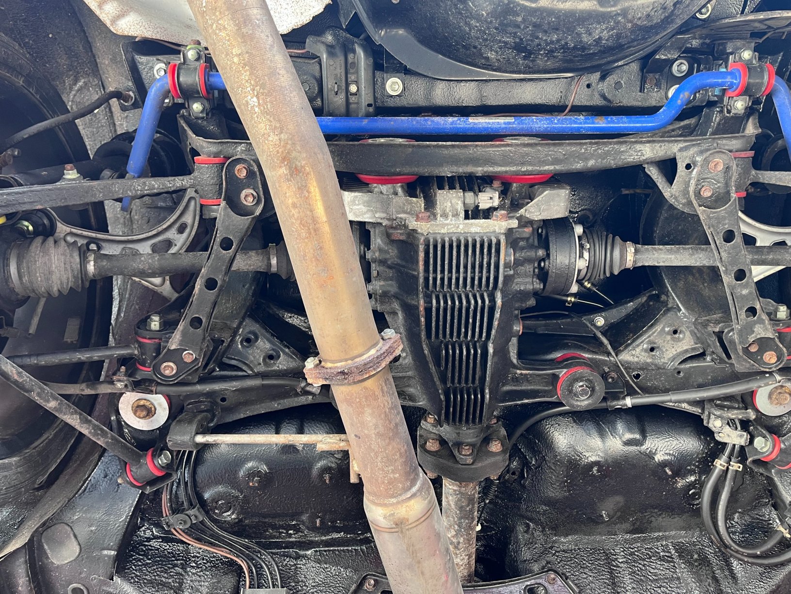
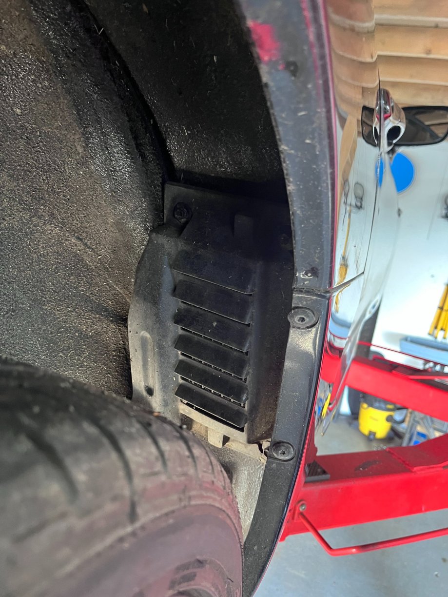
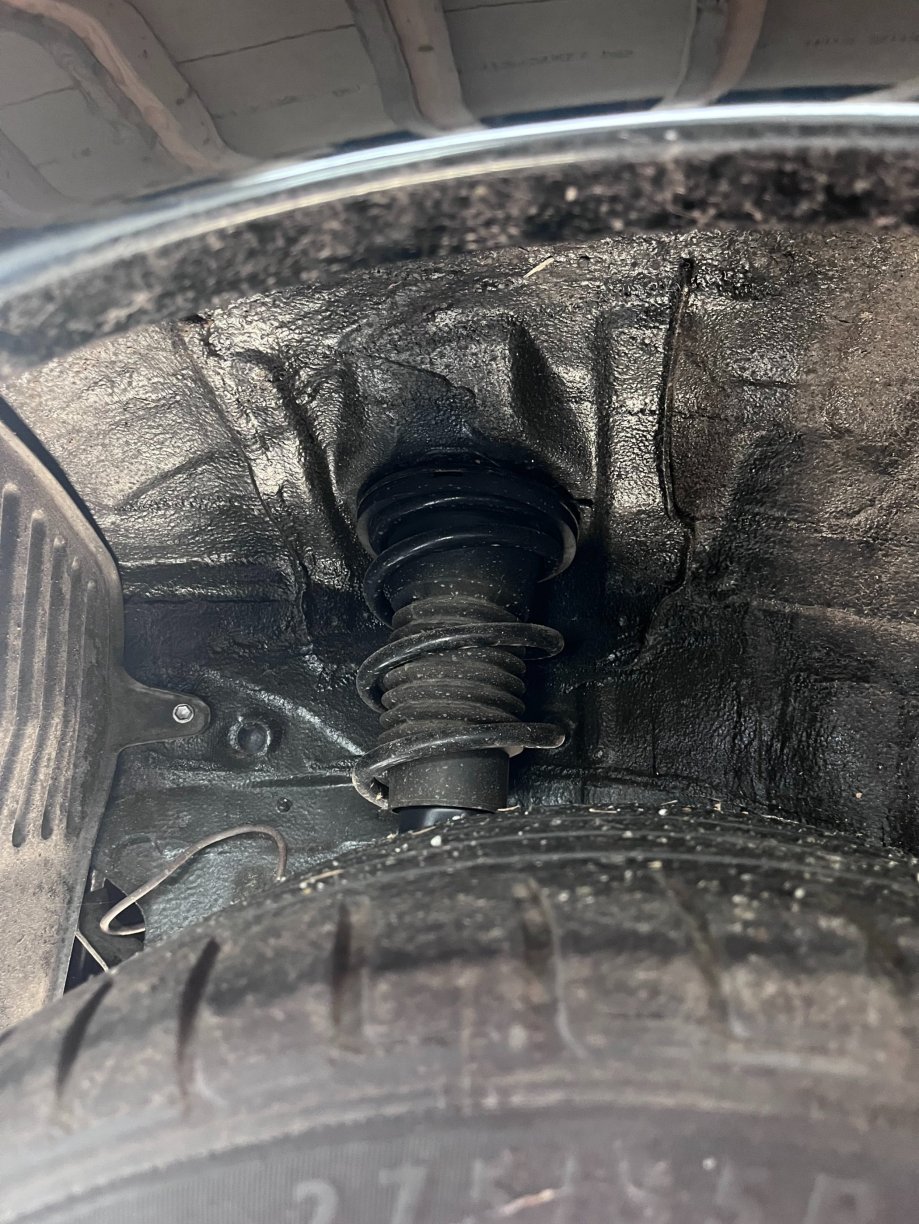
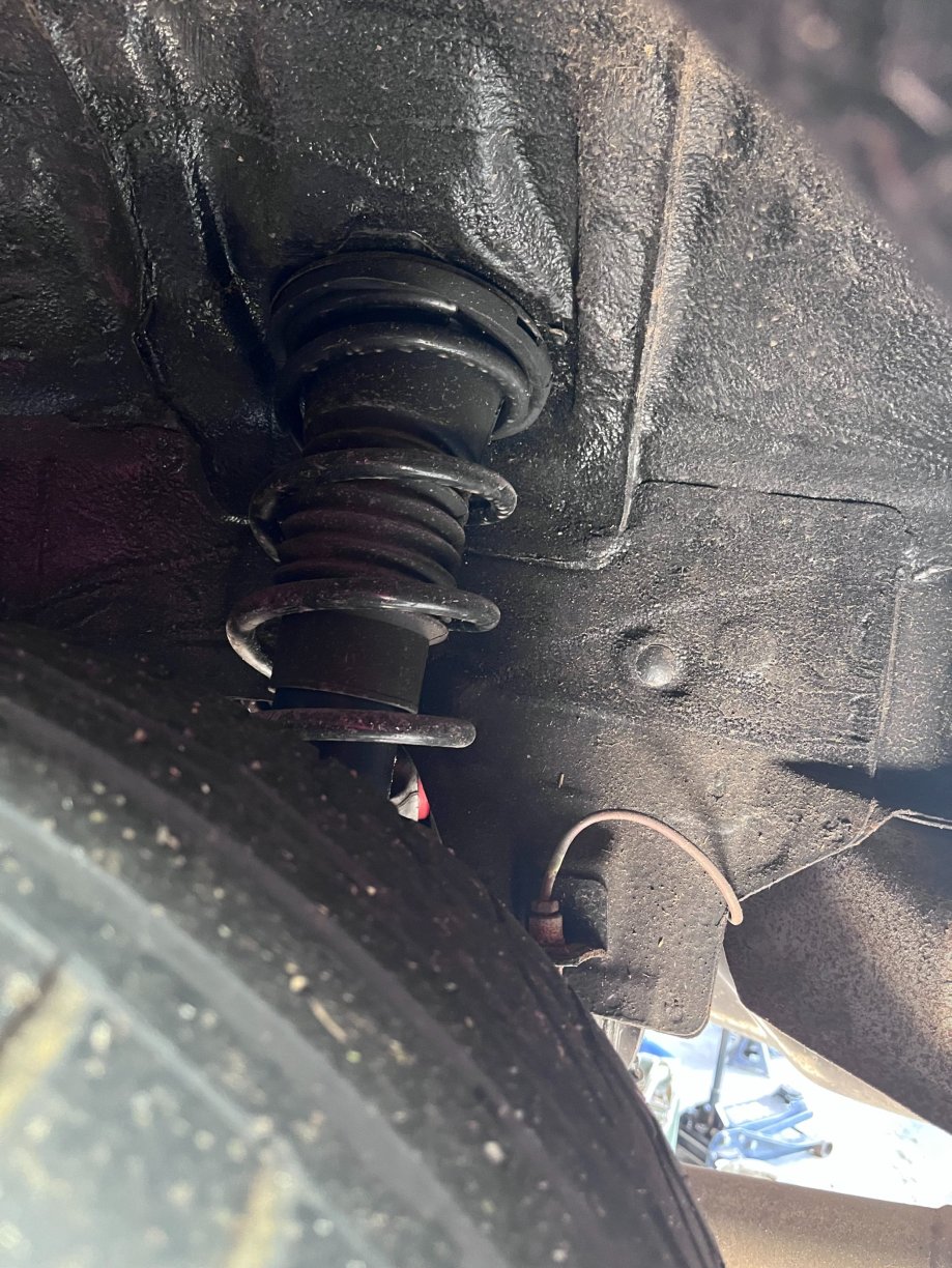
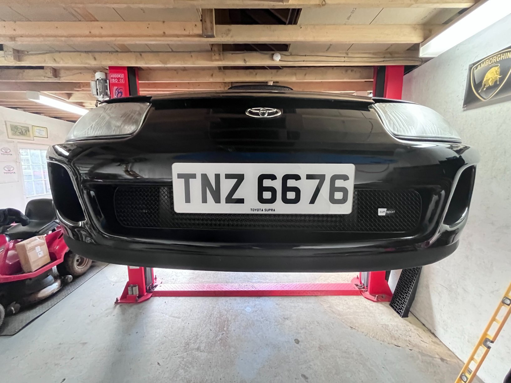
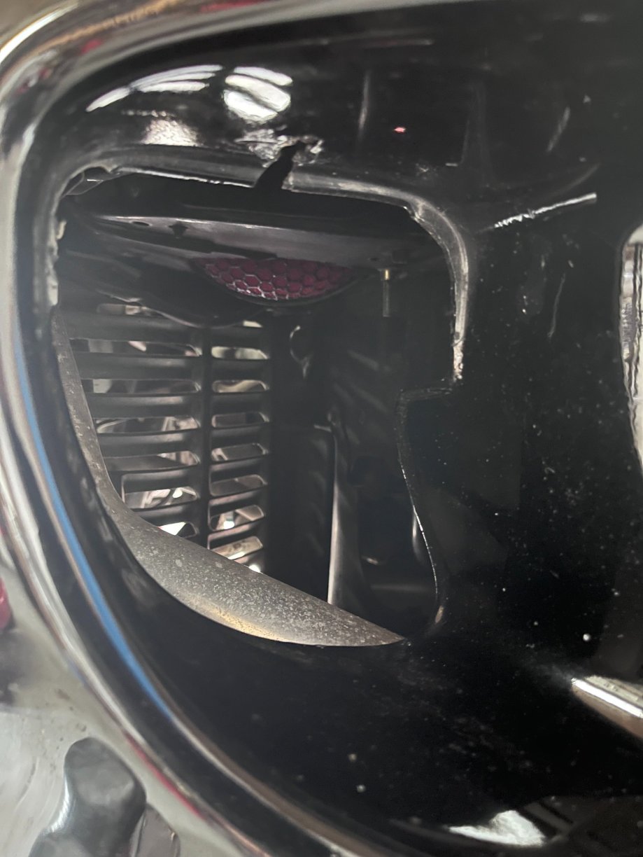
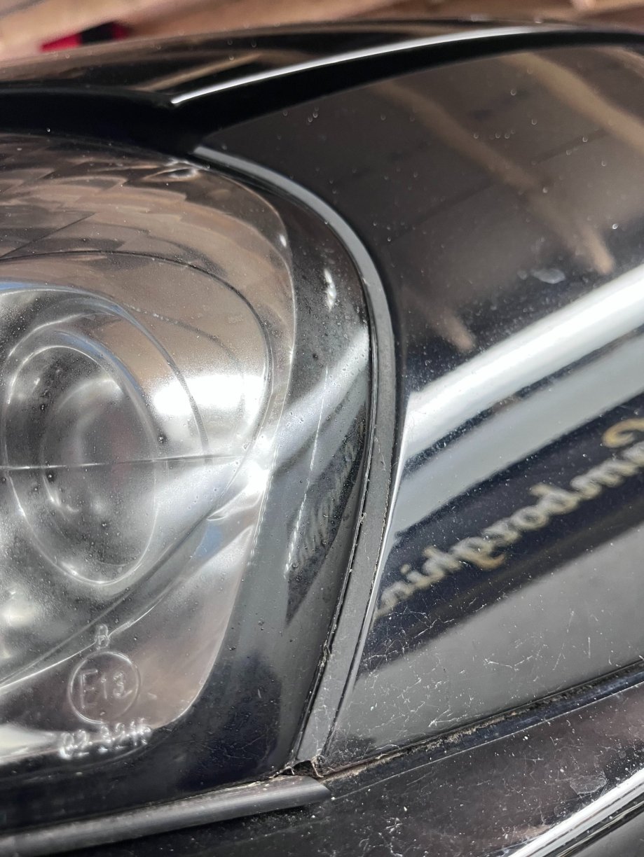
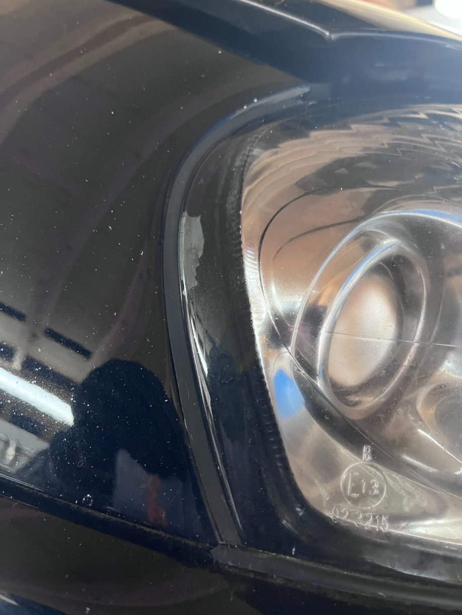
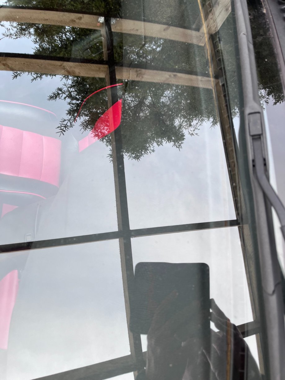
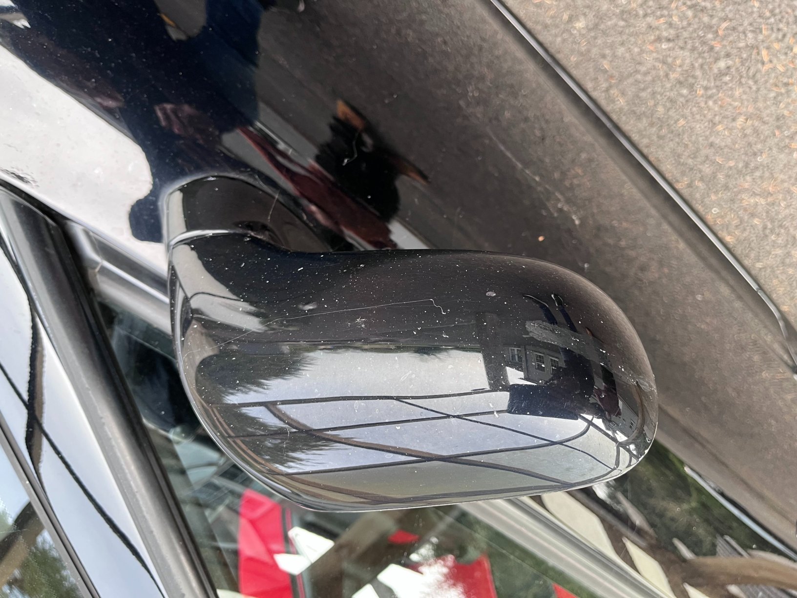
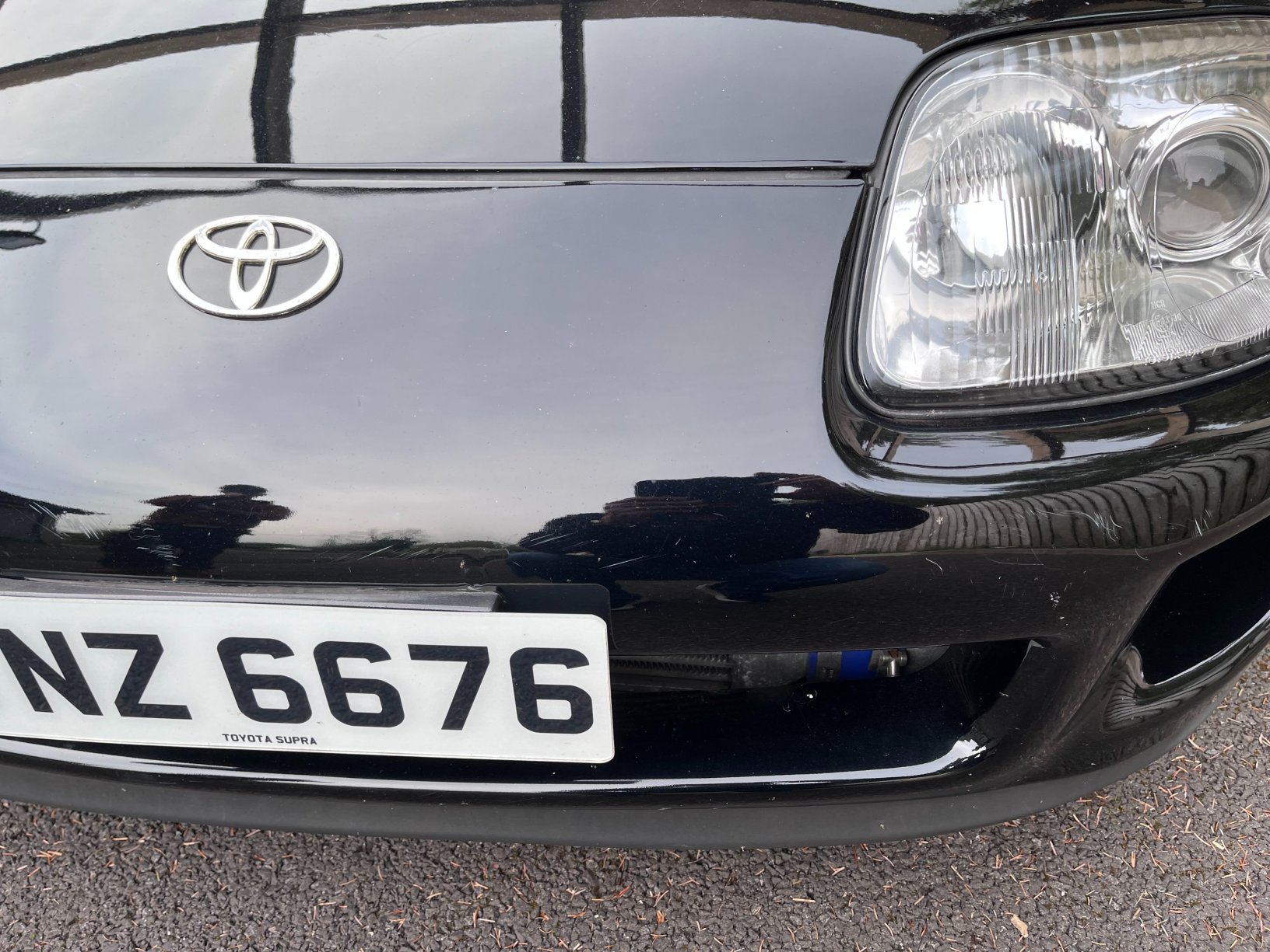
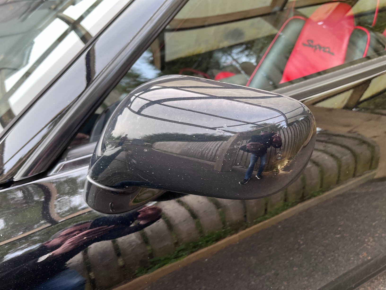
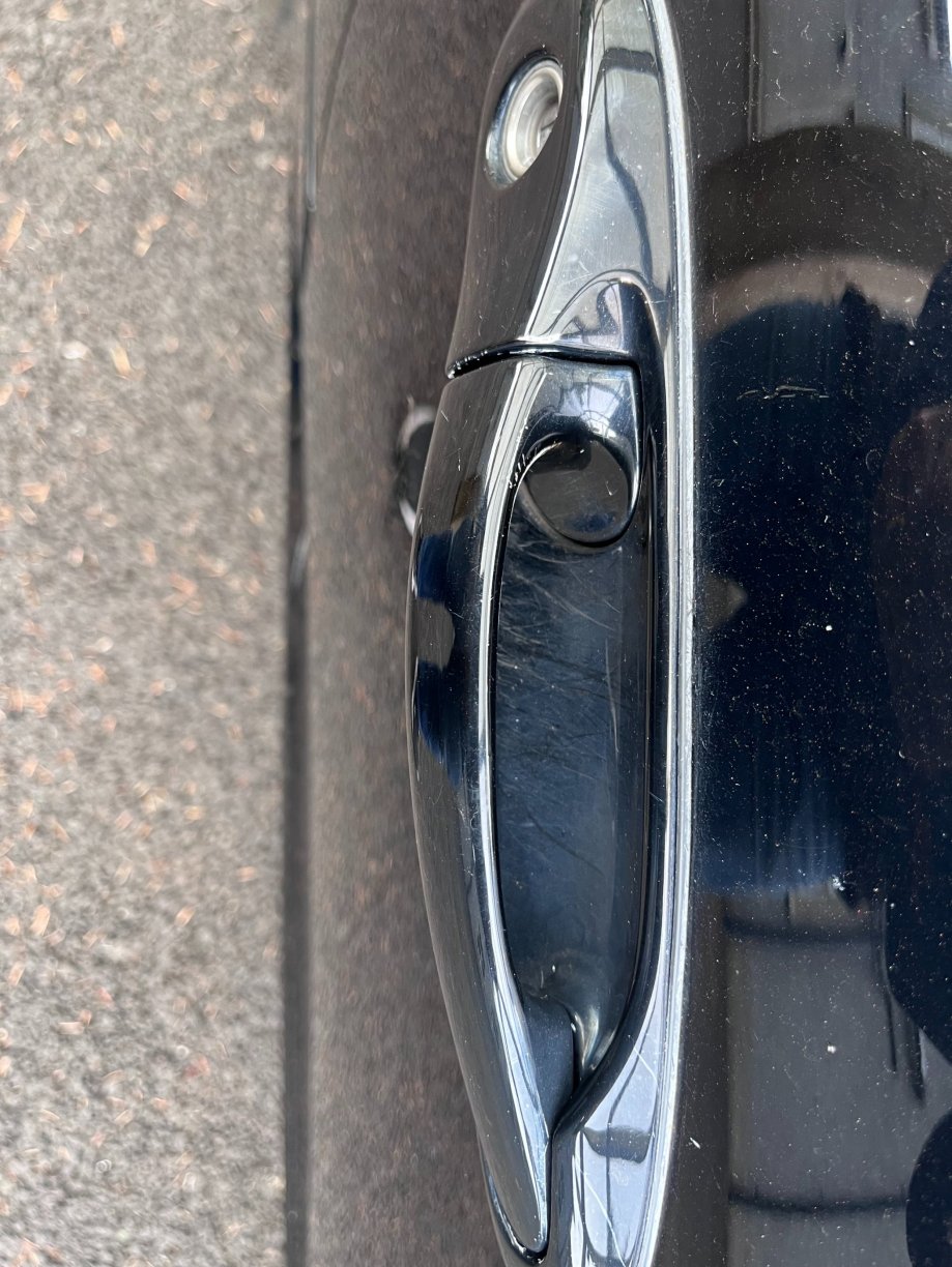
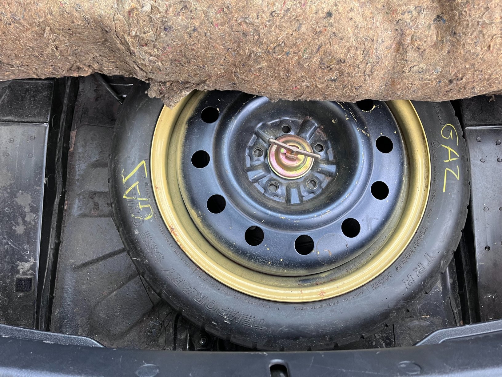
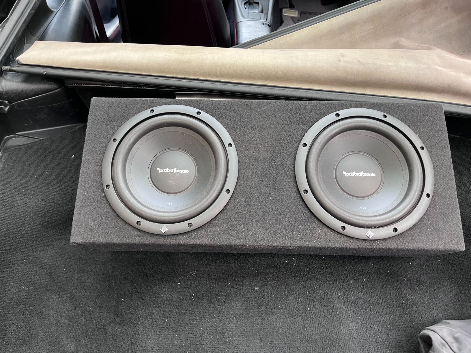
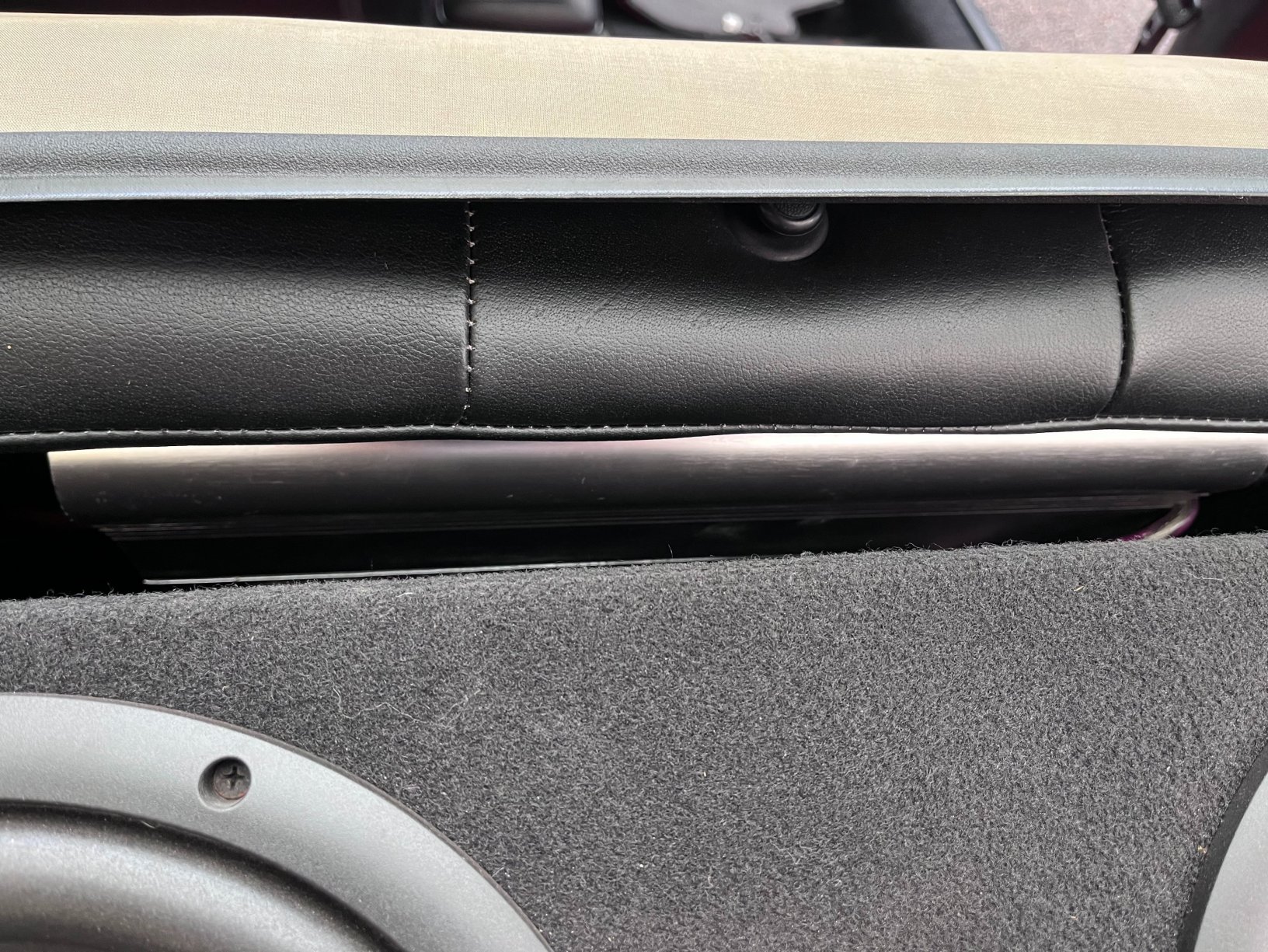
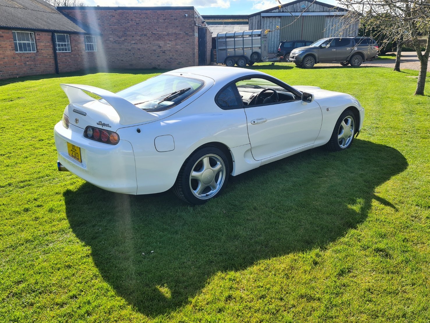
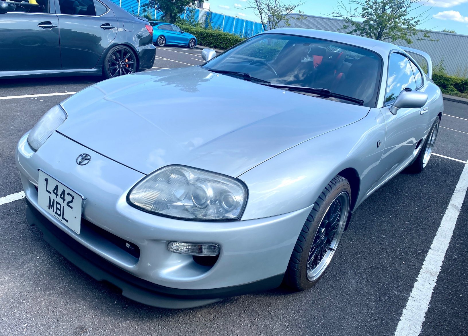
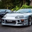
Time to sell as I’ve only put 800 miles on the car in the last seven years and the roads around my home are no longer good enough to enjoy driving it. Also, I always keep it in the garage here and I’m getting tired of moving it in and out all the time. I have owned the car for the last twelve years and it is my second Supra whilst being a member on here. Make: Toyota Supra Model: MKIV TT Auto (UK Spec) Year: 1995 Facelift: No Mileage: 111,906 miles MOT remaining: Full Year to April 2026 Service history: Folder full of history comes with the car. Stamped at new on 3rd August 1995 by Toyota dealer Montys of Sheffield, again by them after 1,000 miles and then full dealer service history up to 2008 at 106,810 miles. Serviced by myself from when I bought the car in 2013, I am a Toyota enthusiast and a qualified mechanic with many years experience with looking after Supras. I am the 6th owner from new. Engine oil replaced using Millers CFS 10W-60 with new genuine Toyota oil filter at 111,699 miles. Only ever used genuine Toyota red coolant, replaced in 2016 when the radiator was replaced. New Denso aircon condenser and radiator were replaced in 2016 along with the radiator support crossmember and rubber feet which had corroded. The stock turbos were both rebuilt in 2018 by MCM turbos due to slight end play movement found during routine check (not turbo failure) along with a host of other related parts including turbo gaskets, oil drain hoses, MAP sensor, etc. The genuine Toyota Timing belt, tensioner, idler pulley and the front crankshaft oil seal were replaced at 111,699 miles (in 2018). The coil packs were all replaced with uprated packs from Whifbitz in 2016 and the NGK Iridium spark plugs and coil pack clips were done at the same time. A new O2 sensor was also fitted and all of the VSV solenoids have been replaced periodically. The brake callipers have all been rebuilt and are in good condition and the brake master cylinder was rebuilt with genuine Toyota parts in 2020, giving a nice firm pedal. The battery was also replaced in 2020 (Yuasa 60Ah). A full rear end rebuild including new rear shocks and springs, all rubber bushings replaced with polyurethane ones, Cusco rear 22mm sway bar, new fuel tank straps, genuine brake hoses, new fuel tank shroud, all brake hard lines replaced with kunifer, all fuel pipes replaced with black aluminium hard lines, new rear wheel bearings, handbrake cables, new rear crash bar, new Walbro 255lph fuel pump, new genuine fuel filter and loads of genuine nuts and bolts was completed recently. The rear diff cooler radiator in the driver’s side rear wheel well was replaced with an identical copy made by Brownlow radiators (old one will come with car for comparison). This preserves the not very functional but original cooler (pump still works). Car’s Location: Ballymoney (N. Ireland) Modifications: BPU Fully De-catted with a downpipe and Blitz Nur-spec Exhaust Front mount intercooler Blitz Dual-SBC boost controller (boosted to 1.3bar) HKS intake (new HKS foam filter just fitted) Stock suspension all round except for the Cusco rear anti-roll bar and drop links Team Dynamics 18 inch multispoke wheels New front wiper arms with Lexus aero blades in 2014, also painted the plastic cowl at the same time. Interior – the interior has been converted from the original cream leather and carpet to red and black leather with a genuine UK-spec black carpet. The cream interior was in really bad shape and just wasn’t practical to keep. I bought the leather seat covers on here from a group buy and got hold of a spare set of seats to replace all the cream plastic parts with black ones. A new sound system including Alpine head unit, front and rear speakers and a pair of subs in the boot has been fitted. I do still have the original double-din head unit which can come with the car. The subs are easily removed if you are not into that sort of thing and the amp is screwed to the back of the rear seats behind it. The electric aerial is wired into the active spoiler switch on the dash so you can have the head unit on and the aerial down. Most of the rubber hoses in the engine bay have been replaced with silicone ones. The EGR valve has been deleted (I have the valve if you are mad enough to want to put it back on). Badges - (controversial) the badges have all been replaced with genuine gold Toyota badges except the Supra turbo badge on the back which is still black. The gold badges were supposed to look good against the black paint but aren’t to everyone’s taste. I have the original badges which will come with the car if the new owner wants to put them back on (wouldn’t blame them). HKS FCD fitted to stock ECU The car has never been dyno’d but it should be putting out around 400bhp which is plenty for me and the stock traction control system to deal with. The front indicators have been moved into the main headlight cluster in place of the front fog light, so the two orange blobs have been removed from the front bumper recesses (I have these and they will come with the car). The orange side indicators have been replaced with clear ones (have these too). Straightforward to reverse this if you don’t like it. There is a genuine TRD roof spoiler which isn’t fitted in the photos but will be for the sale. Other assorted parts (including new front brake disc back plates, Zunsport grilles and genuine TRD rear spats) are available to be sold with the car if the asking price is met. This includes the second catalytic converter should the car ever need to pass a catalytic emissions test. It goes through the standard MOT emissions test fine without it. The paintwork is in generally good condition as the roof, rear quarters and tailgate jamb were recently repainted by a very good local bodyshop due to lacquer peel. The front bumper has some scratches on it and could do with a repaint if you are fussy (see photos). The door mirrors are horrible for some reason and definitely need repainted. The engine undertray was missing so I installed a SRD set of aluminium undertrays in 2016. These are a blessing (look good and give great protection) and a curse (to remove). The car was transferred to a Northern Irish registration when I bought it in December 2013, some people like these as they have a different format to the English registrations (three letters and four numbers) but if not, the original V5 bearing the original English registration is included with the documentation supplied with the car so it can be reregistered if you want to. The Northern Irish plates are perfectly legal throughout the UK. Good bits: Cheap insurance being a UK-Spec and these are now rare cars. No need for any concerns about corrosion on the underside, just look at the photos. Engine and gearbox are strong, recent compression test results can be provided if needed. Lots of life left in the tyres – Toyo R888 on the front and Dunlop SVP Sport on the rear and the car has just had a full four wheel alignment done last month complete with computer print out. I reinforced the rear jacking points during the rear end rebuild which makes it a lot easier to put the car up on a lift. Comes with a Richbrook soft indoor cover Bad bits: Key – there is currently only one key for the car (no alarm or immobiliser is fitted) and it only fits in the driver’s side door and the ignition obviously. The central locking works but you have to put the key in the door lock to lock and unlock the car. I removed the stock alarm system, intending to fit an aftermarket one but never got round to it. The horrible UK-Spec front headlight washers (horns) were removed by the previous owner and I DON’T HAVE them. If you want to spend 400 quid replacing these to restore some originality then you can. The plastic cover over the top of the engine has been cut and the end part replaced with a clear section so you can see the cams and the belt. These are rare so I tidied it up as best I could and it looks ok but not original. Almost all of the modifications were done by the previous owner and so I don’t have the original parts that were removed such as the stock wheels, the active front spoiler and the headlight washer horns. The front bumper and door mirrors need to be repainted. The aircon was not regassed after the condenser was replaced (never needed in Northern Ireland). The dashboard is suffering from the common swelling problem which exposes the underside around the plastic vent (see photos). It is only visible from the outside looking in and is unfixable without removing the dash. There is very slight delamination at the edge of the headlights, not enough to prompt a refurb yet but it will be needed in the future. See photos. The front mount intercooler still has blue silicone pipes at the bottom, I have changed all the others over to black, this is hidden pretty well by the Zunsport grille if you choose to fit it (see photos). The installation of the HKS intake by the previous owner necessitated cutting a small section of the front inner wing as shown in the photo – this is good as it feeds cold air directly to the intake but it can also be bad from the originality perspective. The Cusco rear sway bar is blue and the suspension bushes are all red which doesn’t match brilliantly with the rest of the rear underside. The boot floor doesn’t have any of the original foam inserts or spare wheel cardboard cover, just the mat which is in good condition. My last UK spec didn’t have these either so I’m not sure if they even came with them from new. The rear crankshaft oil seal is also leaking very slightly (doesn’t drip) and there may be another small oil leak at the gearbox somewhere or it could all be coming from the one leak at the crank seal. The steering wheel is original and showing signs of wear and could really do with a recovering/renovation. The front suspension hasn’t been touched in my time owning the car and has normal surface corrosion as you would expect. It is functionally fine with no knocks or creaks or any other noises. PRICE £35,000 sold as seen. Please PM for contact details.


 2 points
 -
Great work. You'll no doubt have discovered the vast array of body plugs and grommets on the underside of the car!2 points
-
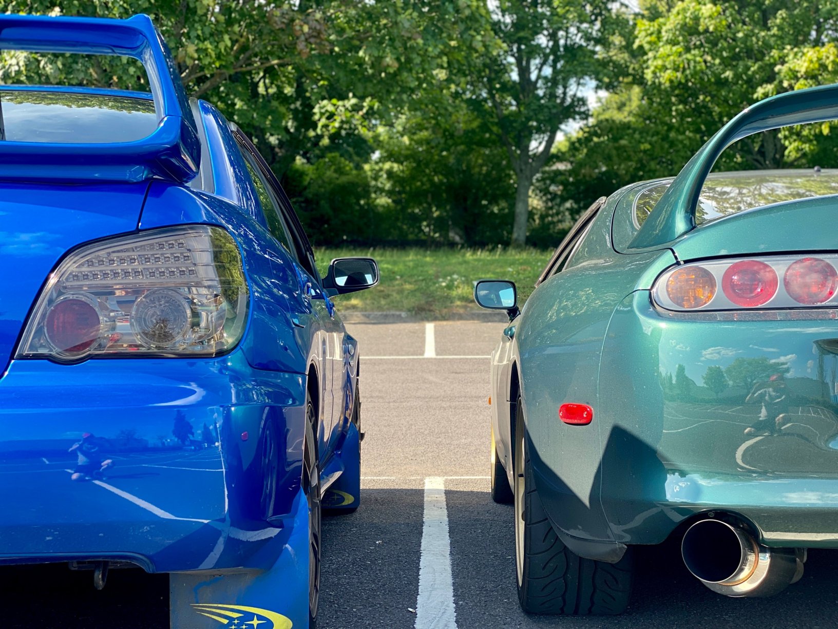
Here's a picture of me next to it. I'll never forget that day
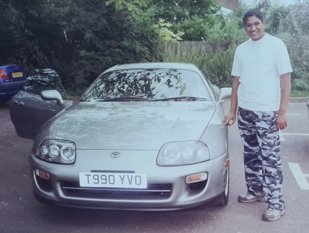 2 points
 -
Looks like a decent enough list!2 points
-
I'm just such a hero I could do it all by myself2 points
-
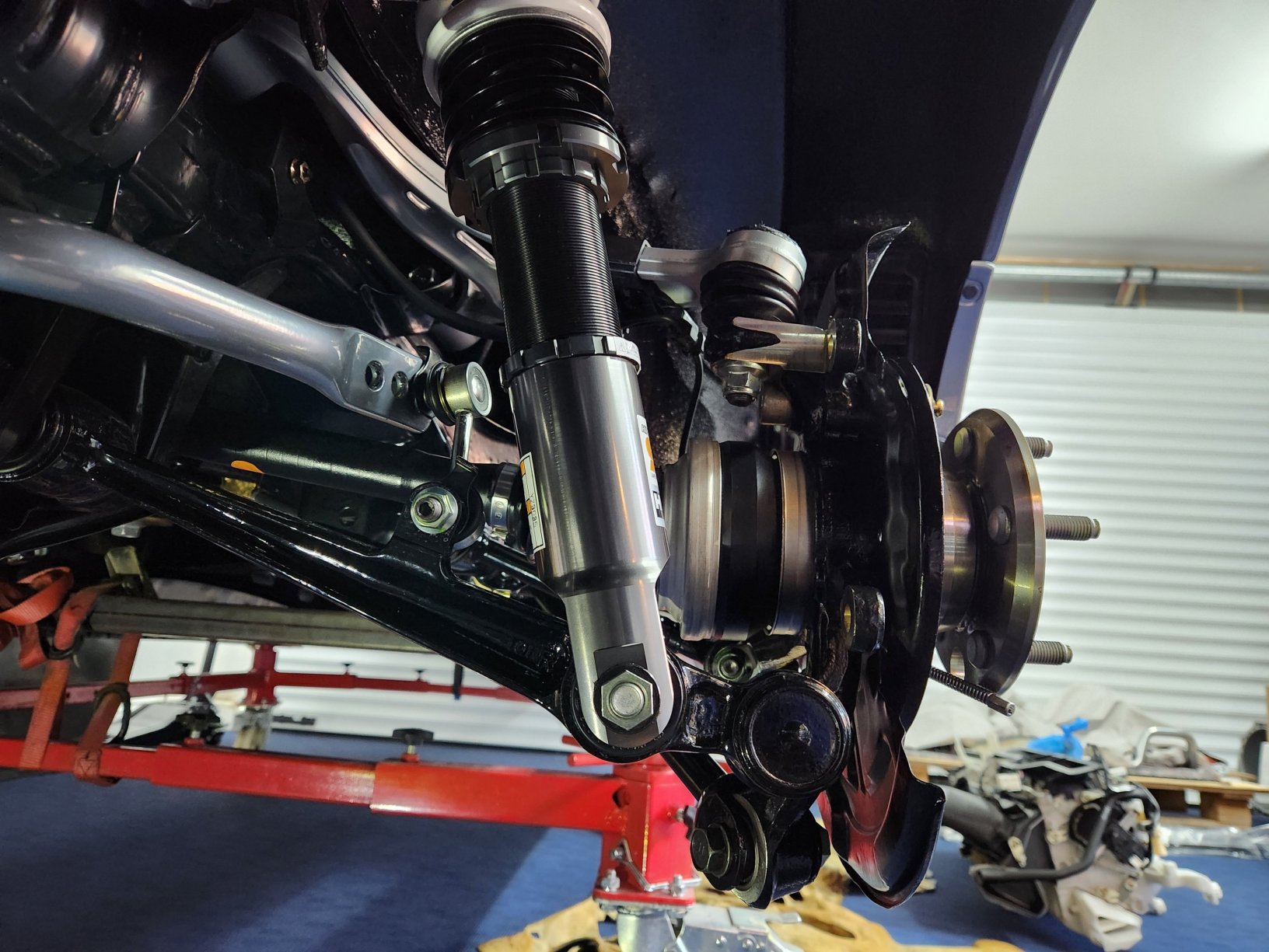
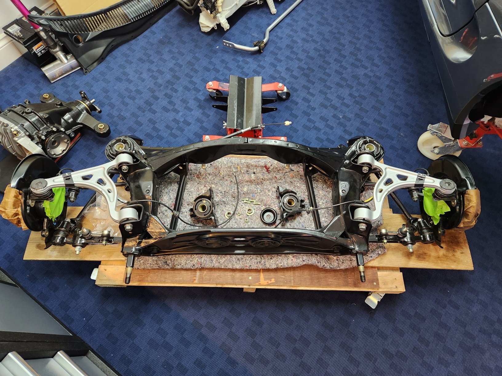
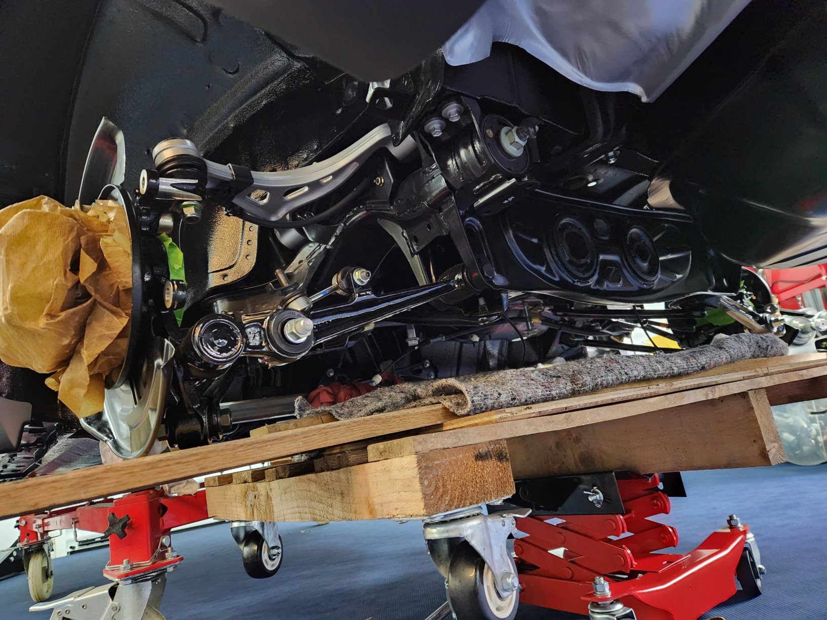
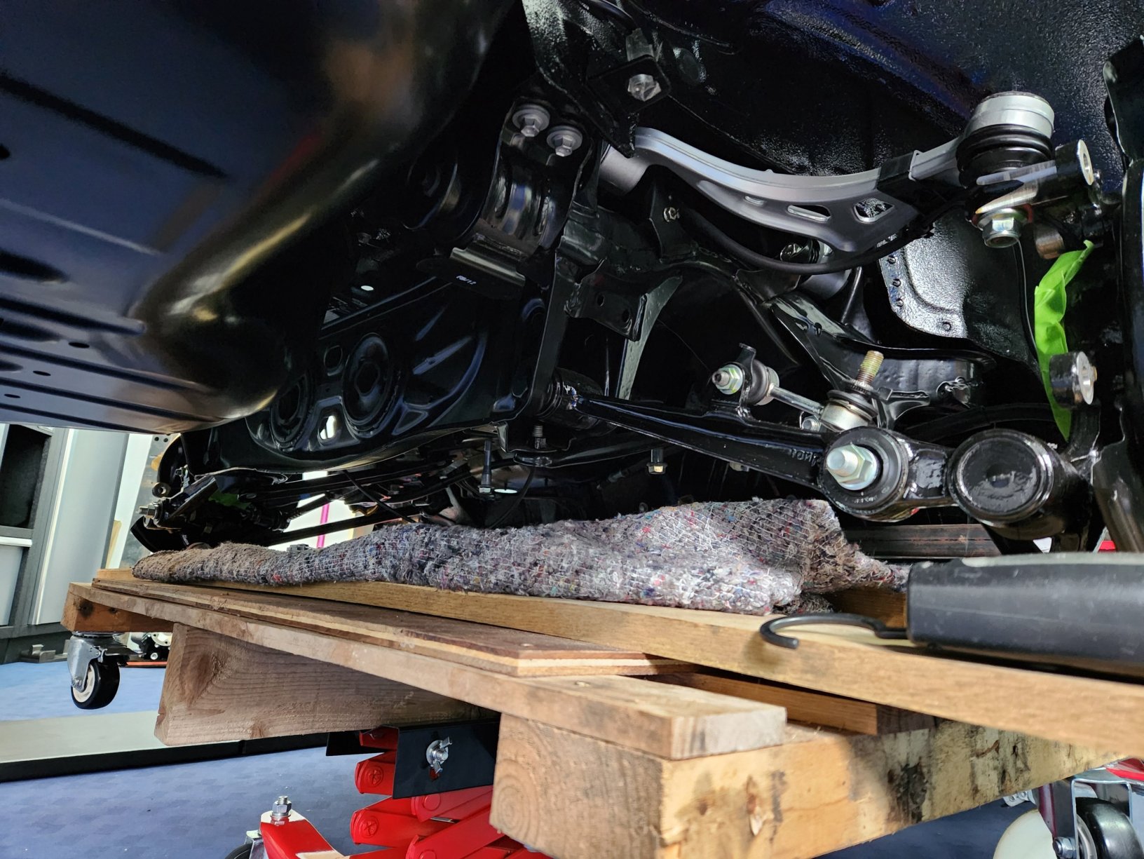
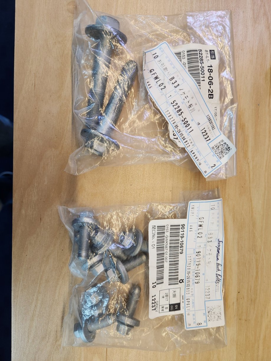
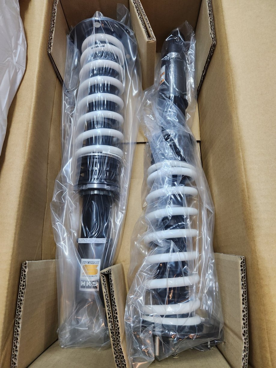
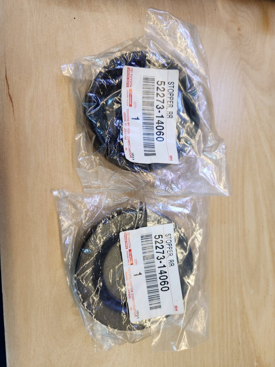
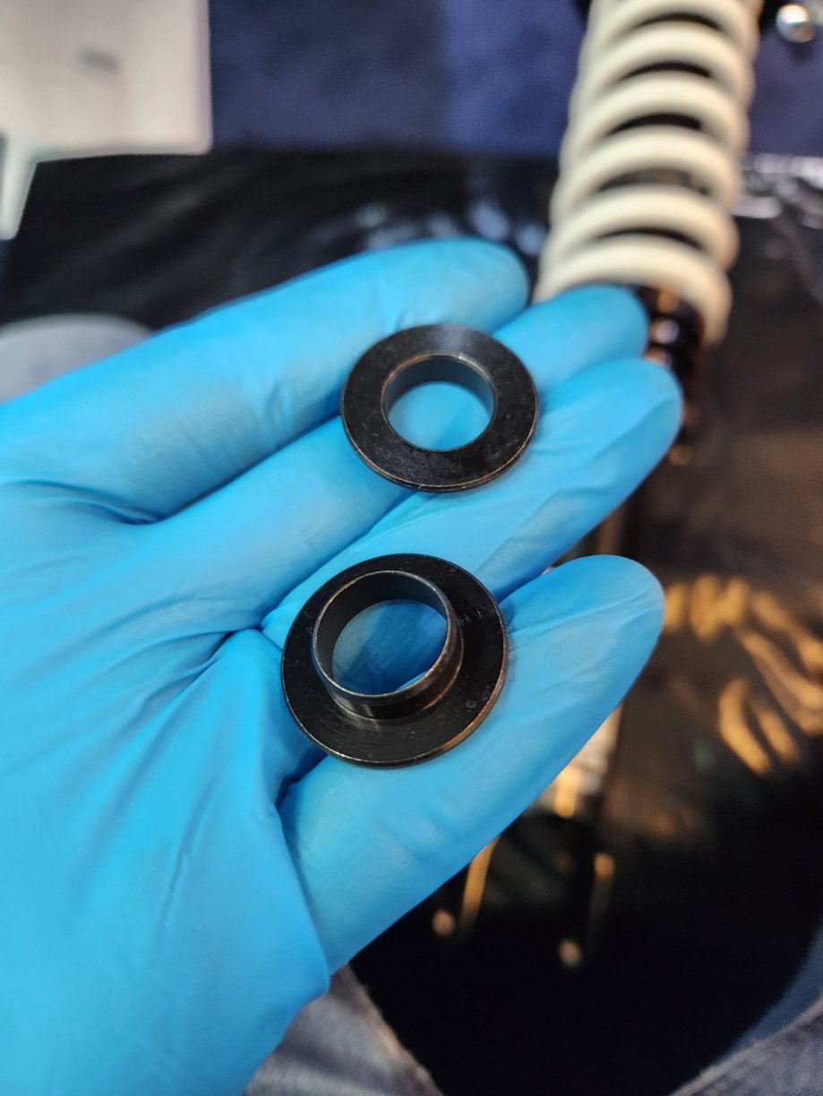
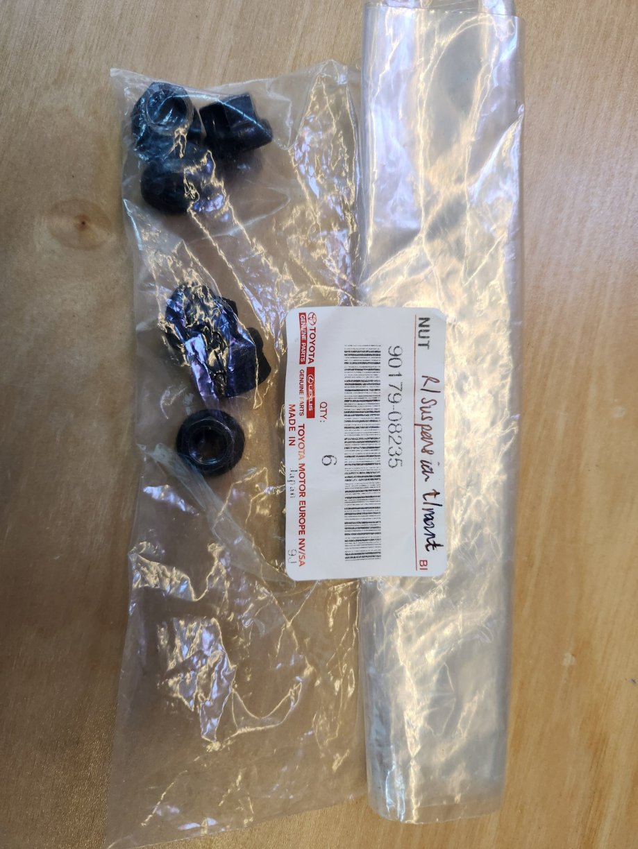
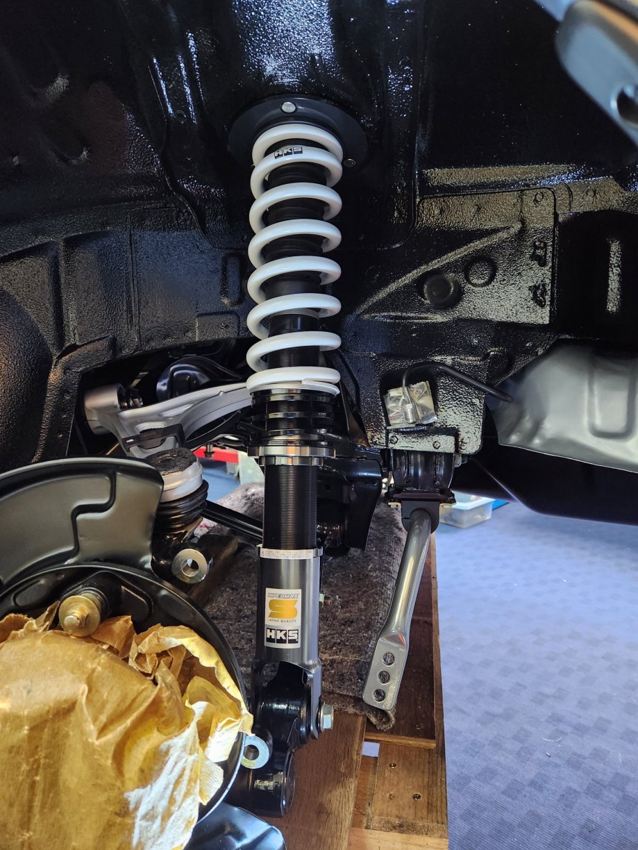
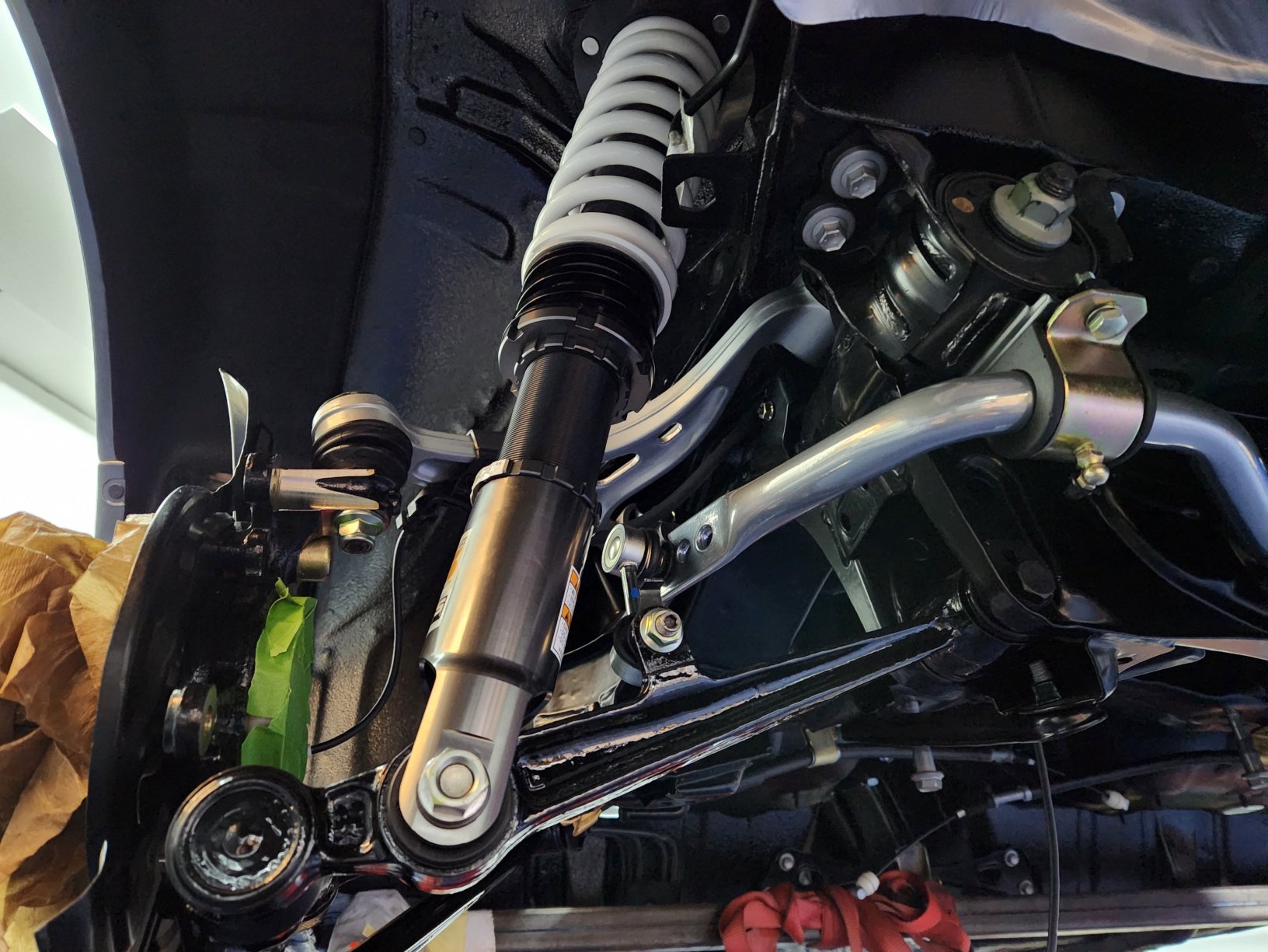
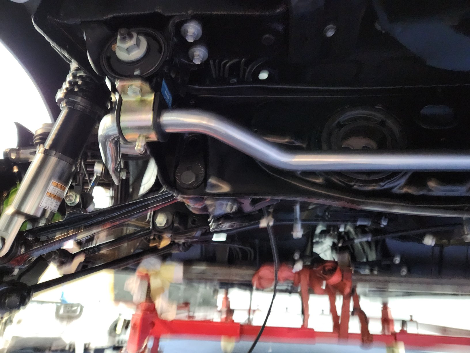
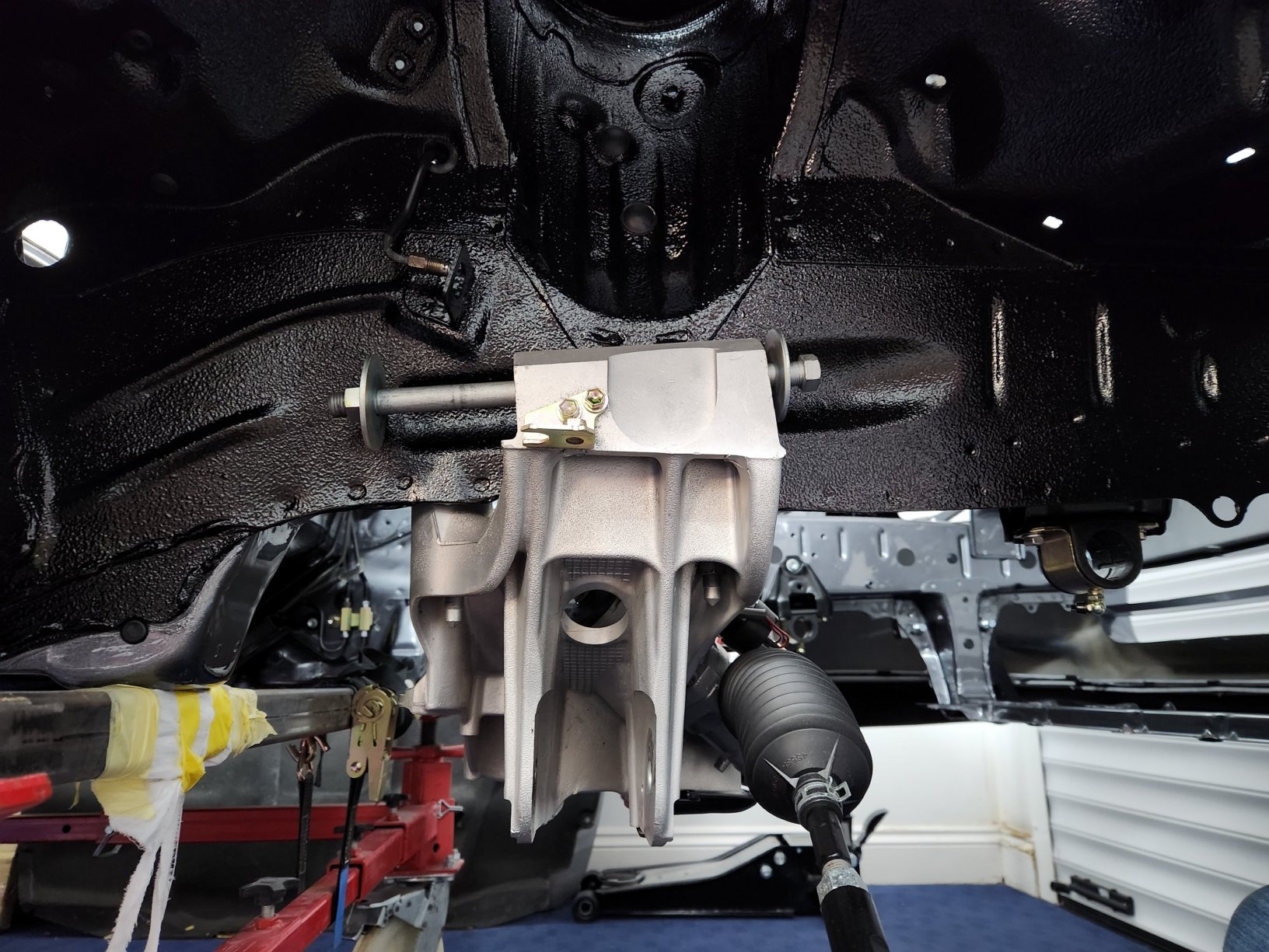
I've also now installed the assembled rear subframe. Info about the subframe rebuild can be found earlier in my build thread. I used new bolts to secure the subframe. The rear 8 x bolts were torqued to 58 Nm. The same torque is applied to the 2 x nuts that secure the rear bushes the the actual subframe. The 2 x front bolts were torqued to 175 Nm. Remeber to install the two lower cups too (easily forgotten). I then installed my new HKS Hipermax S rear struts. I used new bolts, nuts and washers to secure the suspension. There were also a set of spacers that came with the HKS kit to ensure the correct fitment of the rear stud to the lower suspension arm and associated bolt. None of the other suspension bolts have been tightened. I'll do that later when the car is ready to be taken off the body dolly and the wheels installed. I'll jack the hub /knuckle to the correct ride position and then tightened everything up. Final thing was to ensure the ABS sensor leads were pushed up into the cabin from underneath.
 2 points
 -
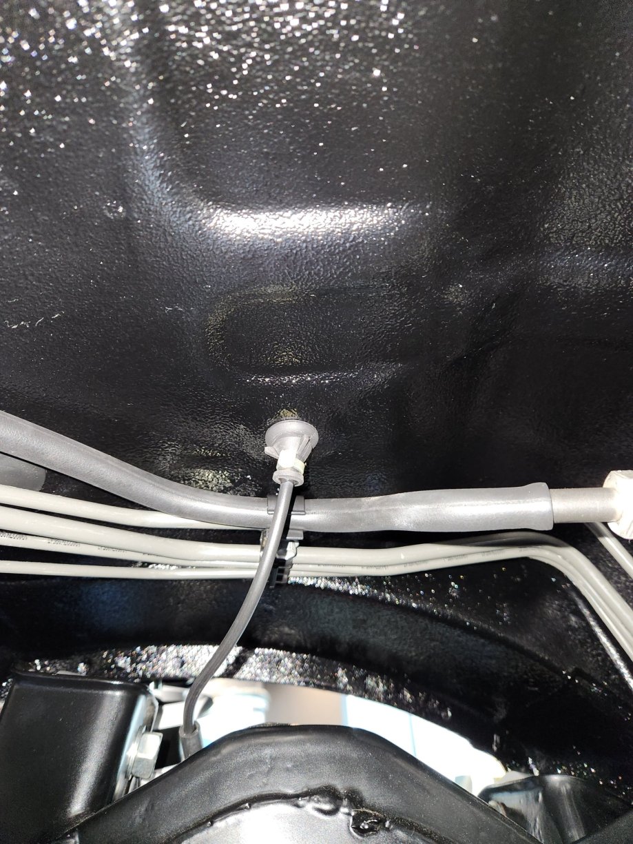
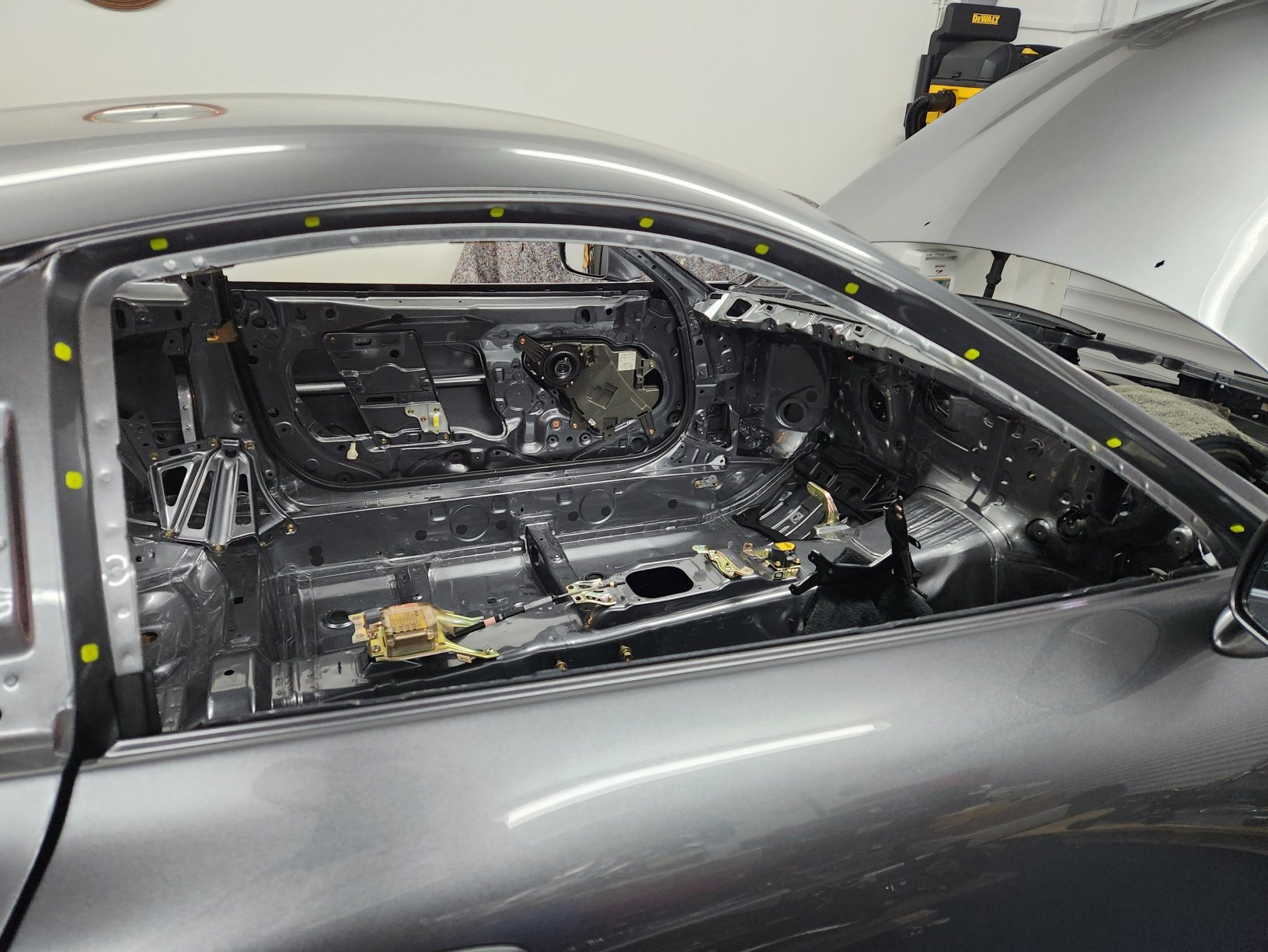
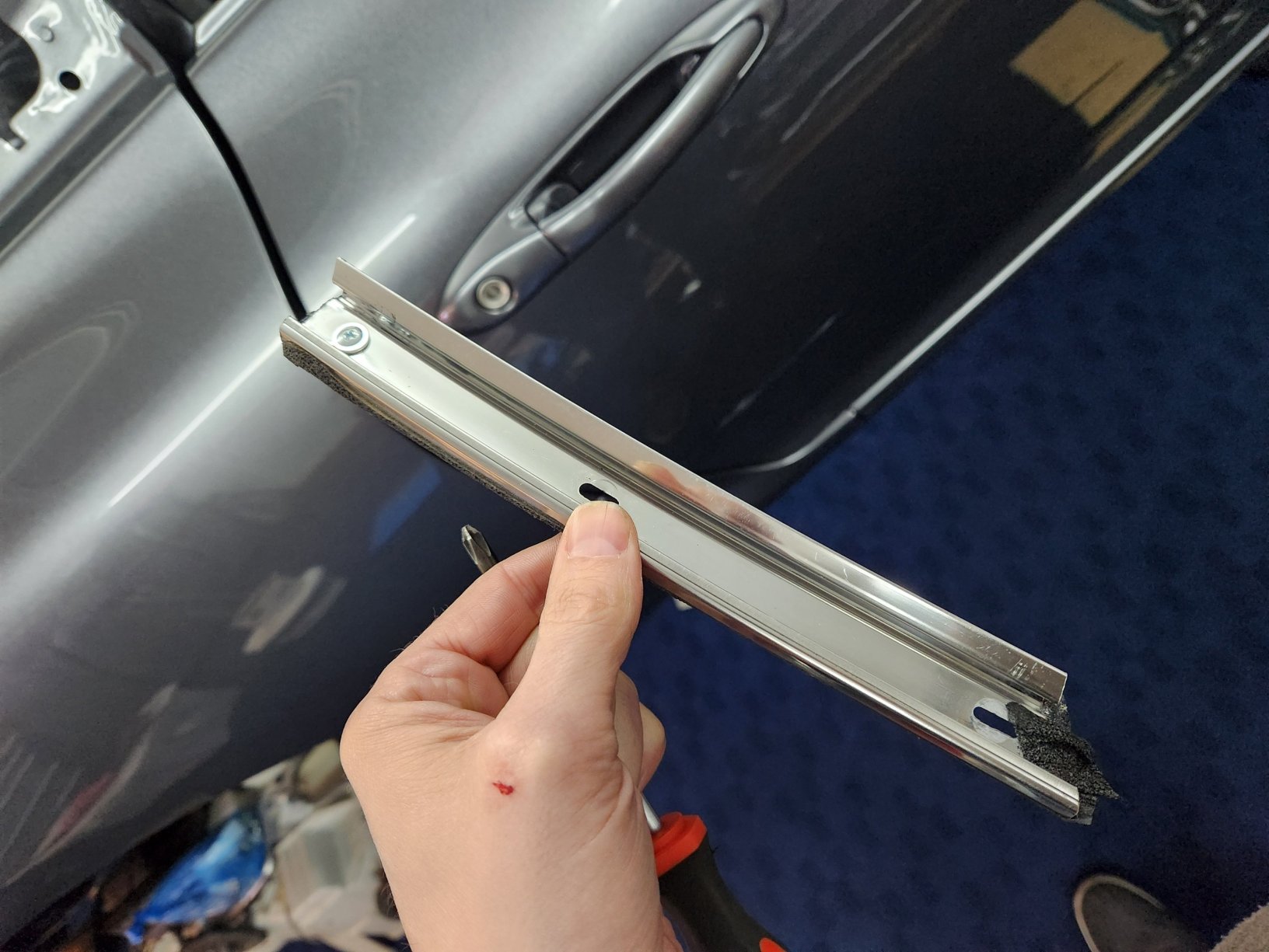
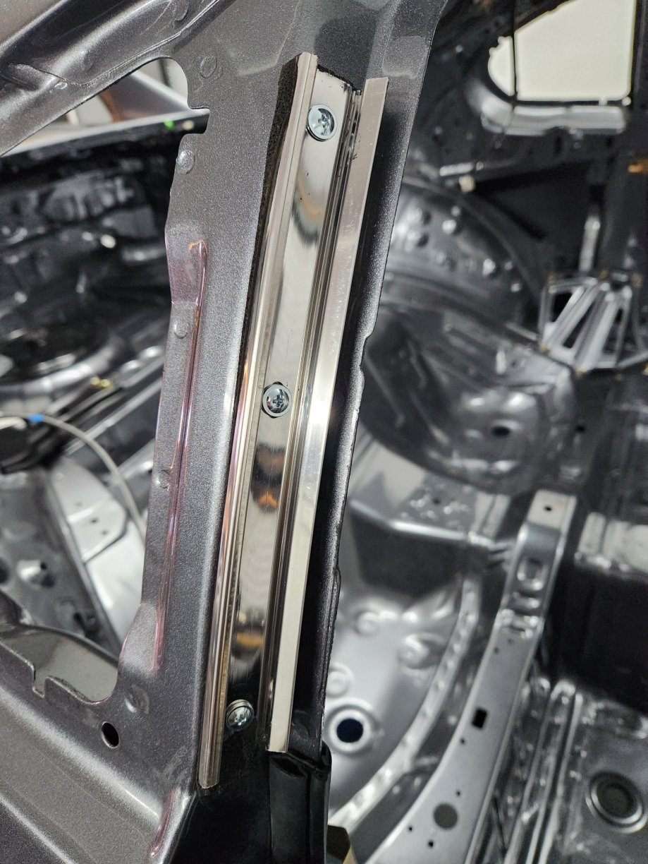
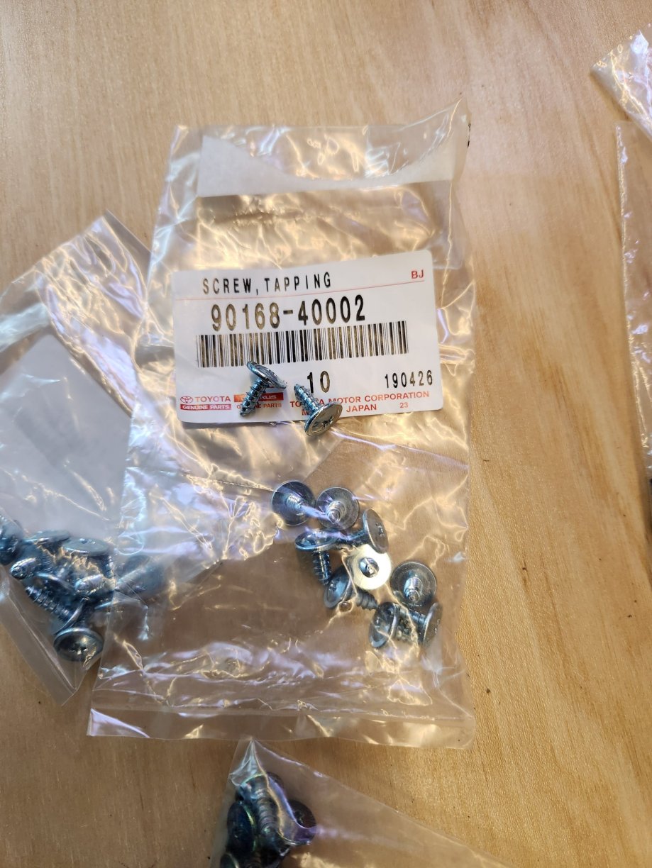
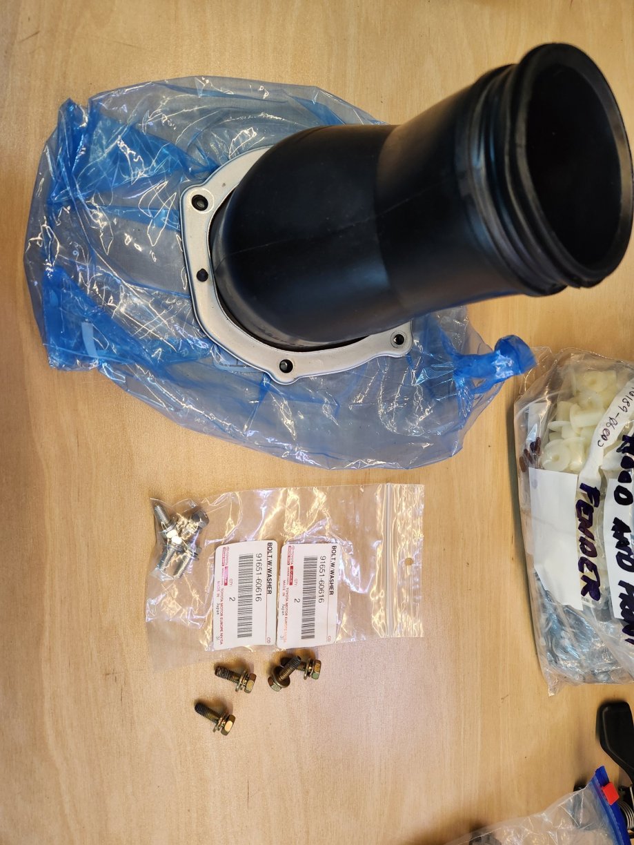
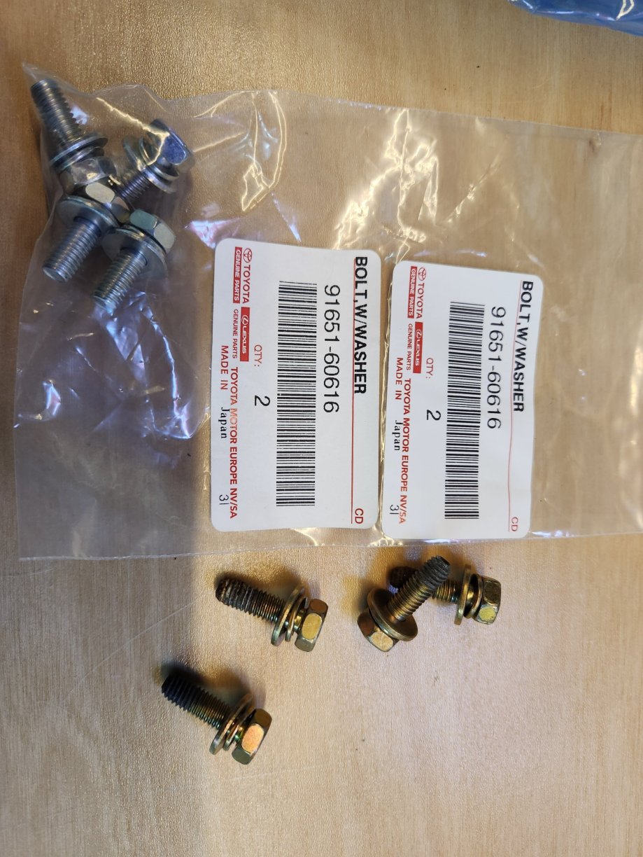
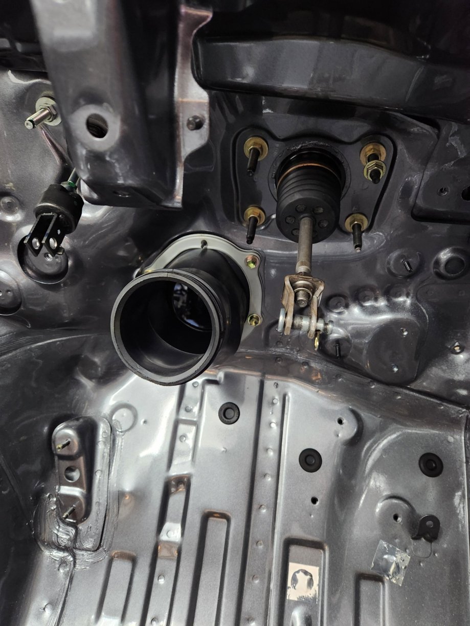
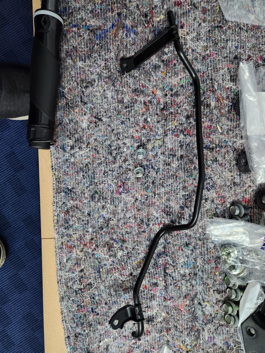
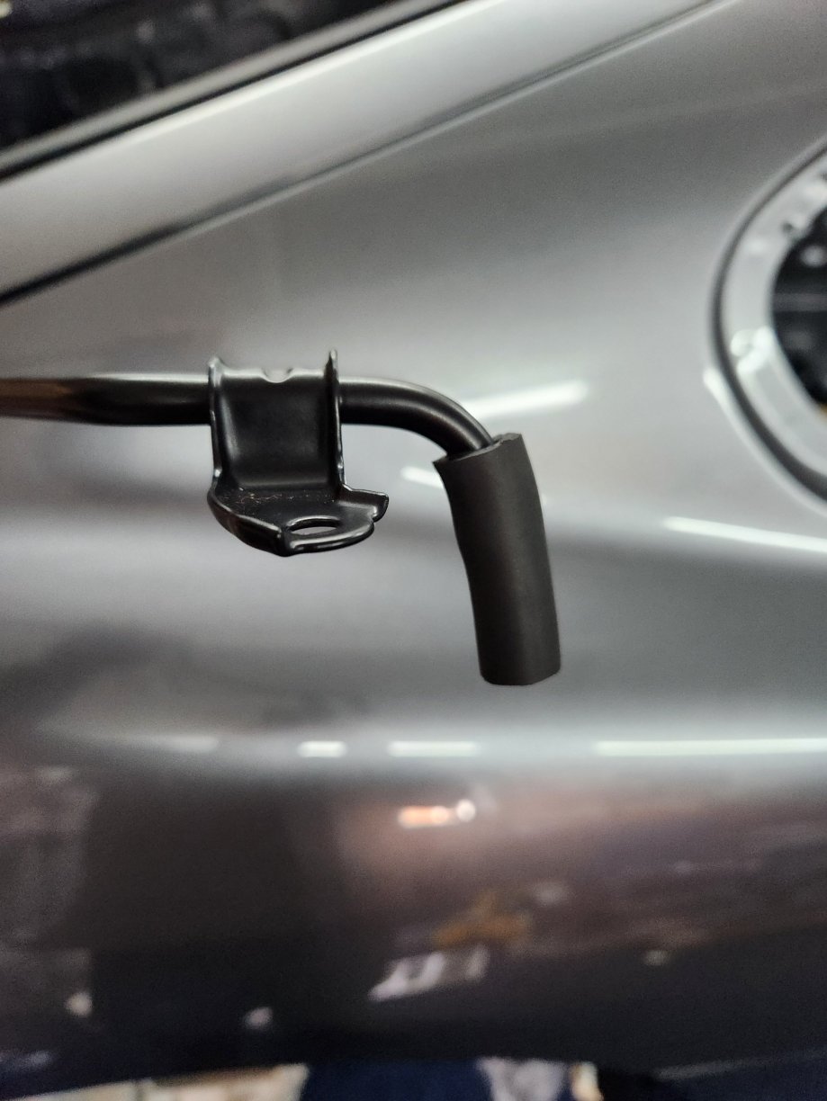
I also did a few other small bits. Window trim. I had previously installed the new yellow grommets, but have put on the front window seal rear guide. These parts are discontinued, so I had to use my originals. Fortunately they are in good order. However, I have purchased new screws. I then installed the steering column boot to the inside of the car. I have reused the boot and bracket, but replaced the bolts.
 2 points
 -
As someone who went down the "gagues everywhere" route many moons ago, I'd advise against having all sorts of info beamed to you at all times. I just found myself constantly worrying about why my AFR's weren't to my inexperienced liking or my oil temps were doing this, that or the other. With the capabilities of ECUs nowadays, I'd make sure it's mapped with all the safetys you can reasonably put on it and just drive the car. If there's a problem, the ECU will do more that you'll be able to at short notice. That being said, I've ordered a digital display that's on it's way over from Aus and am looking forward to installing it and seeing what sort of custom displays I can mess about with I'll just be looking to have something loosely based on the TRD dials with a few extra bits added to fill the empty space (I'm such a hypocrite lol)1 point
-
Really enjoy this thread. Keep up the good work ( and spending )1 point
-
Thanks Kev!1 point
-
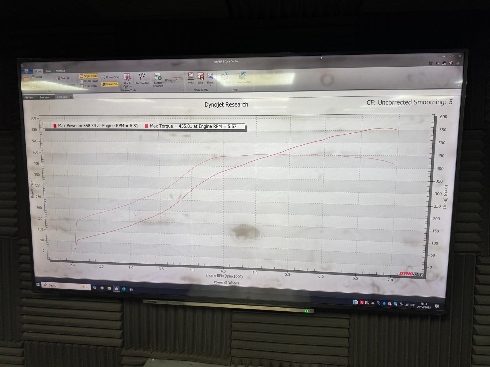
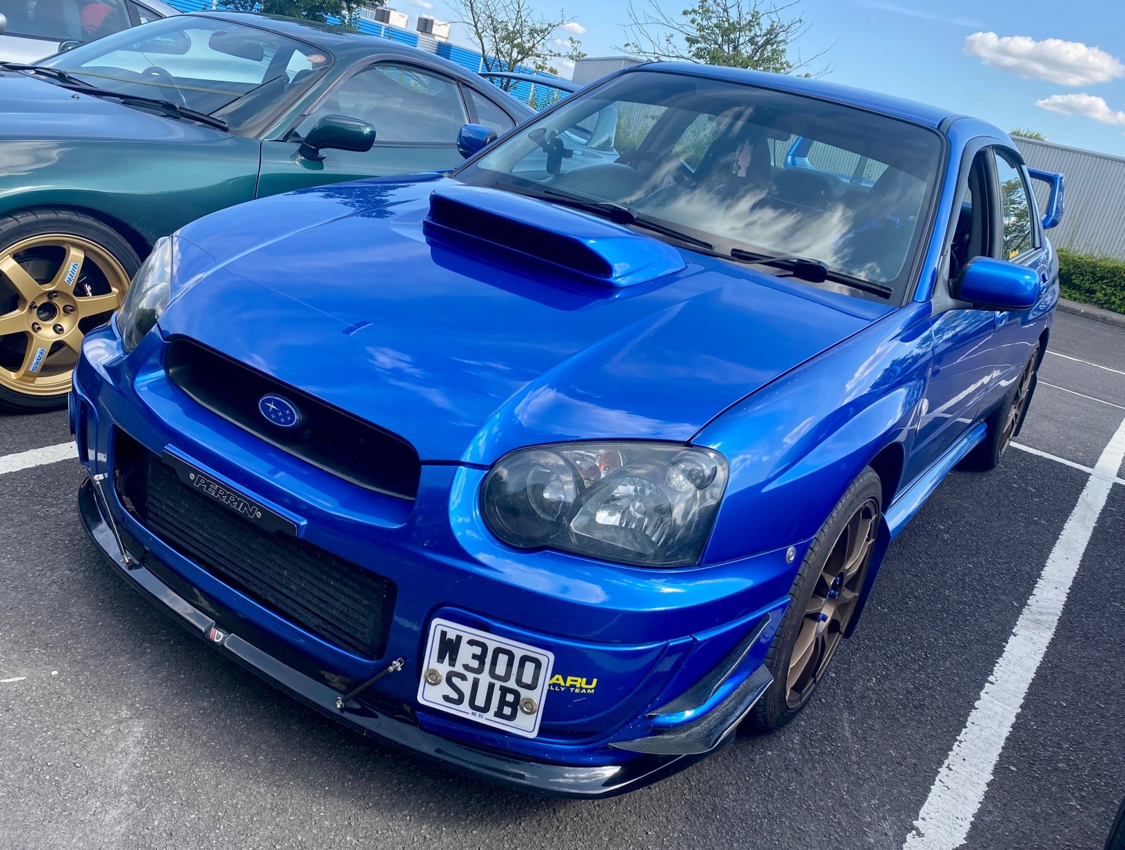
Swapped out the Midpipe which had been crushed from hitting speed bumps etc. this primativelty measure tothe equivilent of a 2.5" diameter. I had a new new 3.5" midpipe made up by an exhaust shop. I put the car on SRR dyno on one of their Saturday Dyno Days, and Charlie advised it was running a little lean for his liking 12.8:1 AFR. I then took advatage of a few deals, a Syvec S7+ from Whiftbitz and 1000cc Injectors and Rail off a memeber, SRD made me up a pre-terminated sensor loom and sensor package, I got all this fitted. Long Story short - SRD Mapped it on all the new bits and it now makes 558WHP @ 1.6bar and 455ft/lb.
 1 point
 -
Hi Steve, it was the large with spoiler.1 point
-
From memory I believe it was the fuse box under kick panel, also had to replace the relay unit behind plastic trim in passenger side of boot, think that failed and caused fuse to blow1 point
-
Hello folks, the last time I started/drove my Supra was probably 2008 - not long after the clubtrackday I organised at Llandow. It needed a few bits of work to make it mint and I decided to store it and save up - and then, well, life happened and after a blur of other higher priorities that's how we got to today. I've found a trusted mechanic and in the next month or two my Supra will be going to him to carefully coax back into life as-it-is, and later one we'll start working on some upgrades to, well, everything, really (full respray, more modern turbo, underbody protection, the list will grow and grow I'm sure...) Anyway - phase 1 is just to get my Supra back up and running. Does this job list look sensible? Did we miss anything? Any 'gotchyas' from those who've experience of storing/restored their cars? Cheers! Steve Here's the message from my mechanic: ------ Very first thing I’d do is decontaminate the exterior. Snow foam, fall out remover etc, (no buffing, waxing/polishing etc) not because I want to see it clean but when I put my wing covers on to work under the bonnet I don’t want it getting scratched with whatever is on there from storage. Then on to the ramp, to give it a full inspection underneath to see what else we are dealing with. Any potential structural body rust, worn suspension bushes, corroded shock absorber main shafts, perishables like brake, clutch and fuel hoses. Vacuum any spiders along the way At this point we won’t know if the clutch assy. Is seized on/off so I will get my bore scope into the bell housing to check. Then the important bit, the engine, pull the plugs out first to see what the bores look like, if ok, then few squirts of oil down there and try to turn over by hand. Check the condition of the cambelt and timing. Check inside the air filter and turbo housing for borrowers and mice, see if the turbo spins freely. If that’s ok then I’d drain the fluids, petrol, engine oil and coolant. Check inside the fuel tank, bench test the fuel pump to see if that works, if all ok then fresh fluids and oil and fuel filter and with the EFI fuse out go for a turn over with plugs out (will have to buy a new battery no doubt) if it sounds healthy and the starter isn’t seized, new plugs in, EFI fuse in, ignition on and check electrical items are operating and then go for a start up. I’m sure there will be little added bits in between I decide to check before doing anything.1 point
-
Haha yep! Some of them I’ve grinded through in error but when I put it back together time will tell what I’ve misplaced or destroyed I think my head is going to be permanently fixed in the lean back looking up pose though. Absolutely soul destroying work.1 point
-
~Sunday 20th April, 12:30pm~ 1. KamaSupra 2. ChrisPank 3. WhiteSupeDan 4. Vinny 5. Big Supes 6. DansMumsSupra +1 7. GeorgySupey 8. James_cbr +1 (Maybe) 9. Big_SingleBen (Maybe) 10.1 point
-
Agreed. You've got everything I can think of covered. I would probably change the cam belt and tensioner regardless of how it looks, having been sat for so long.1 point
-
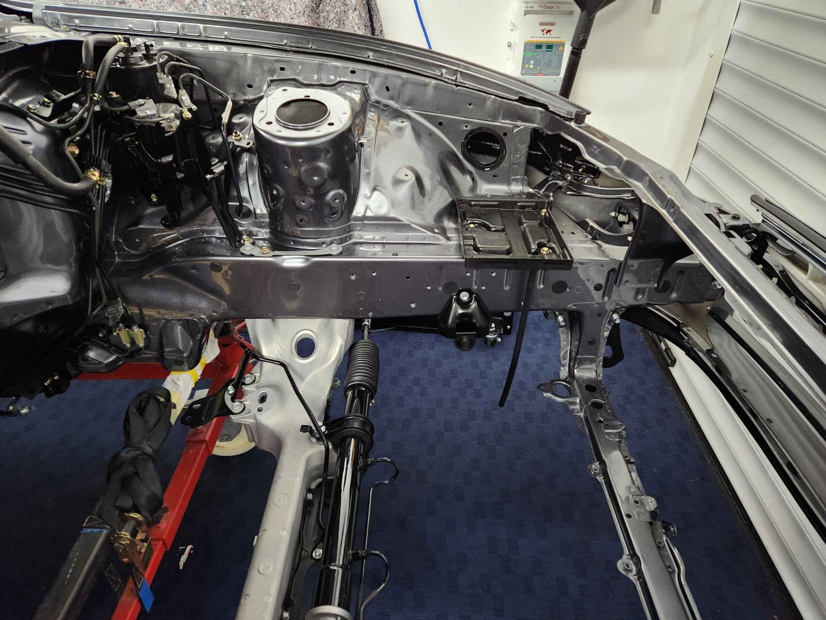
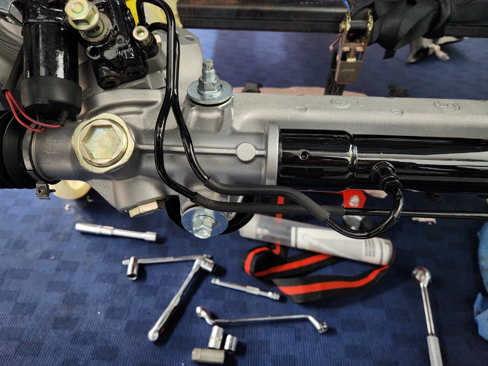
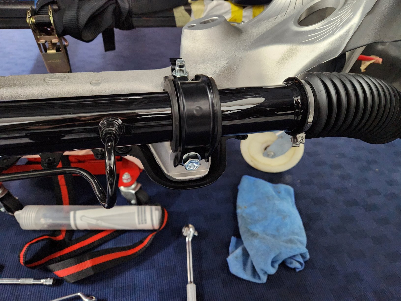
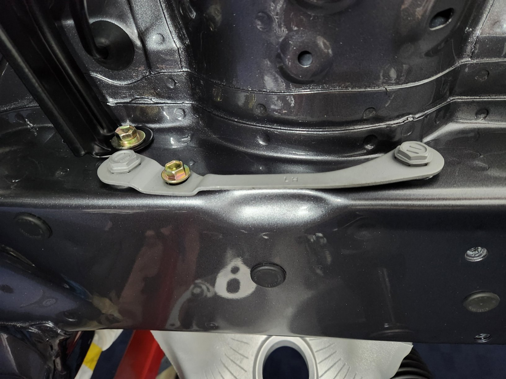
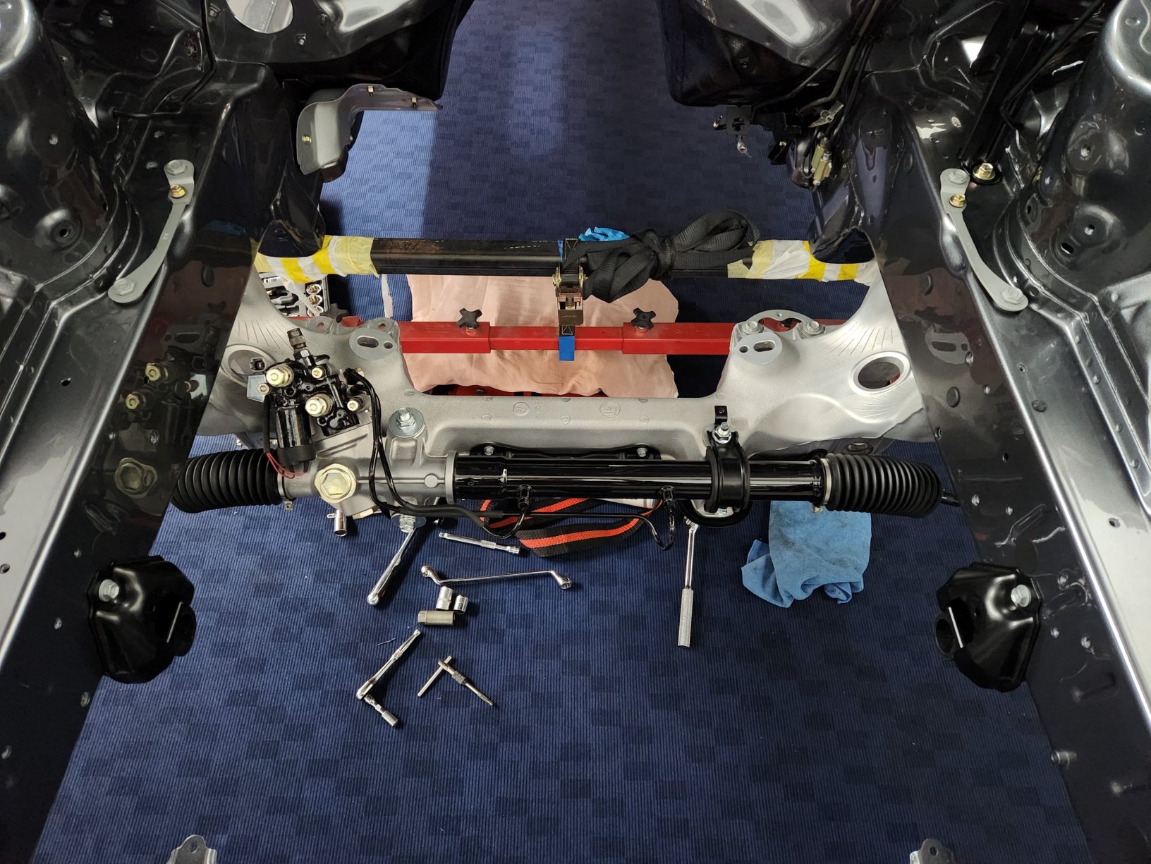
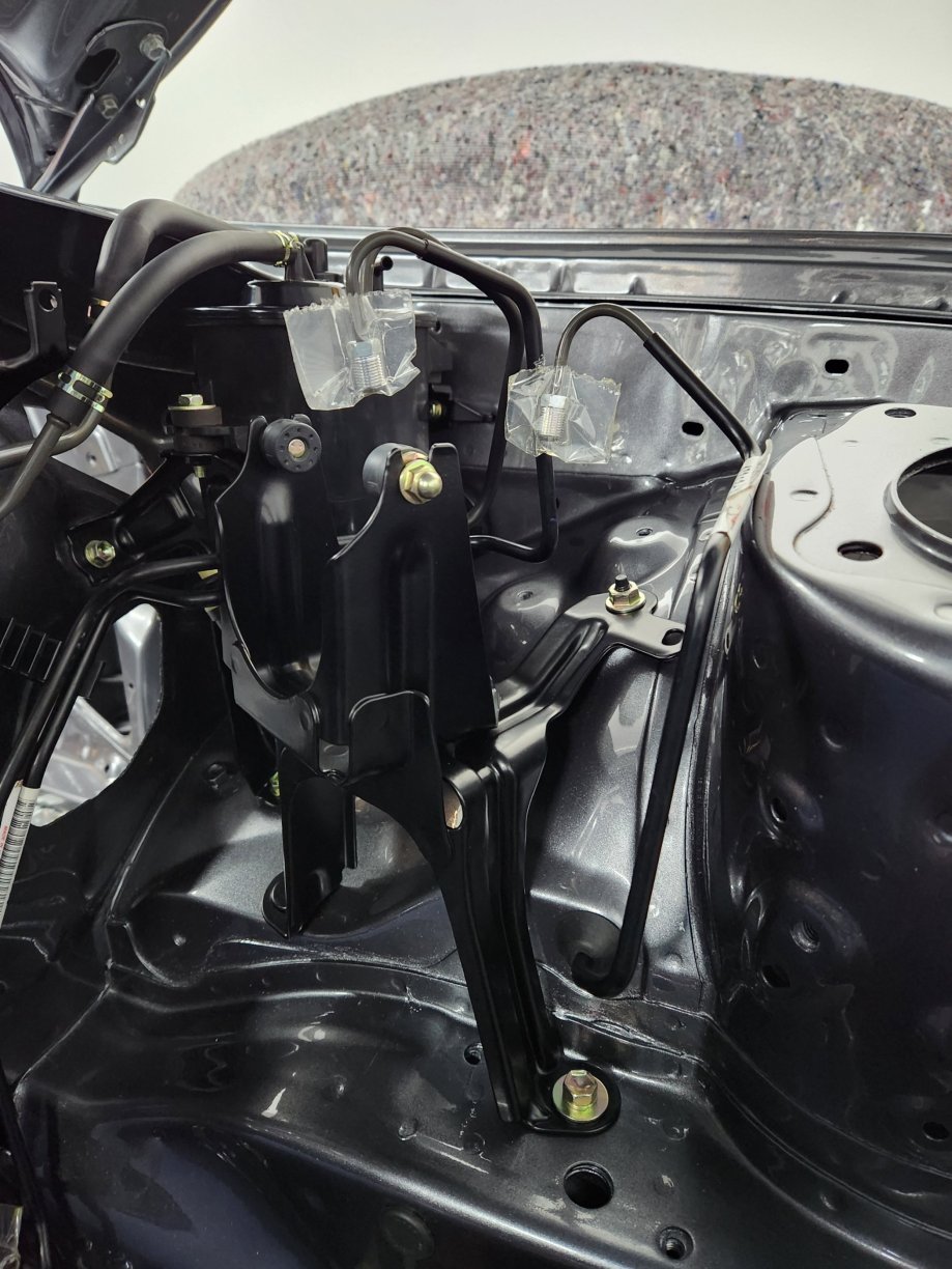
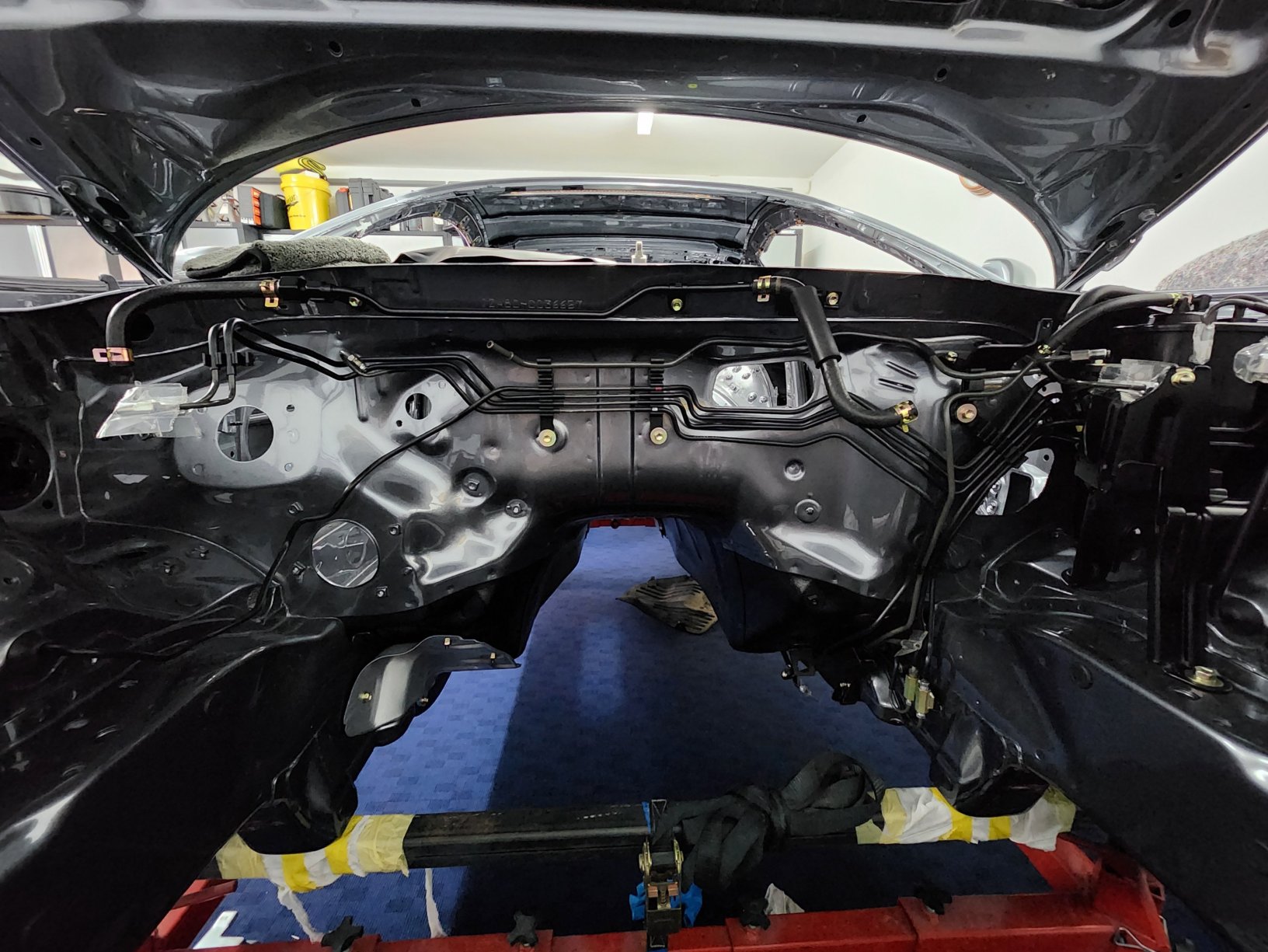
I've now installed the bulkhead pipe work. I've also installed the aluminium part of the front subframe. More details about the work and parts for the subframe can be found earlier in the thread. Main subframe bolts torqued to 125 Nm. Steering rack bolts x 4 torqued to 75Nm.
 1 point
 -
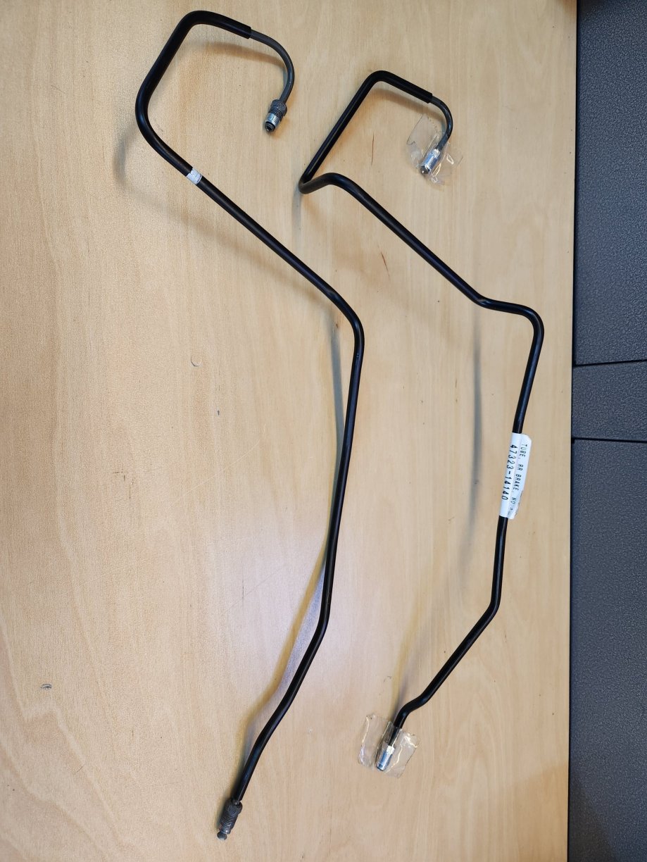
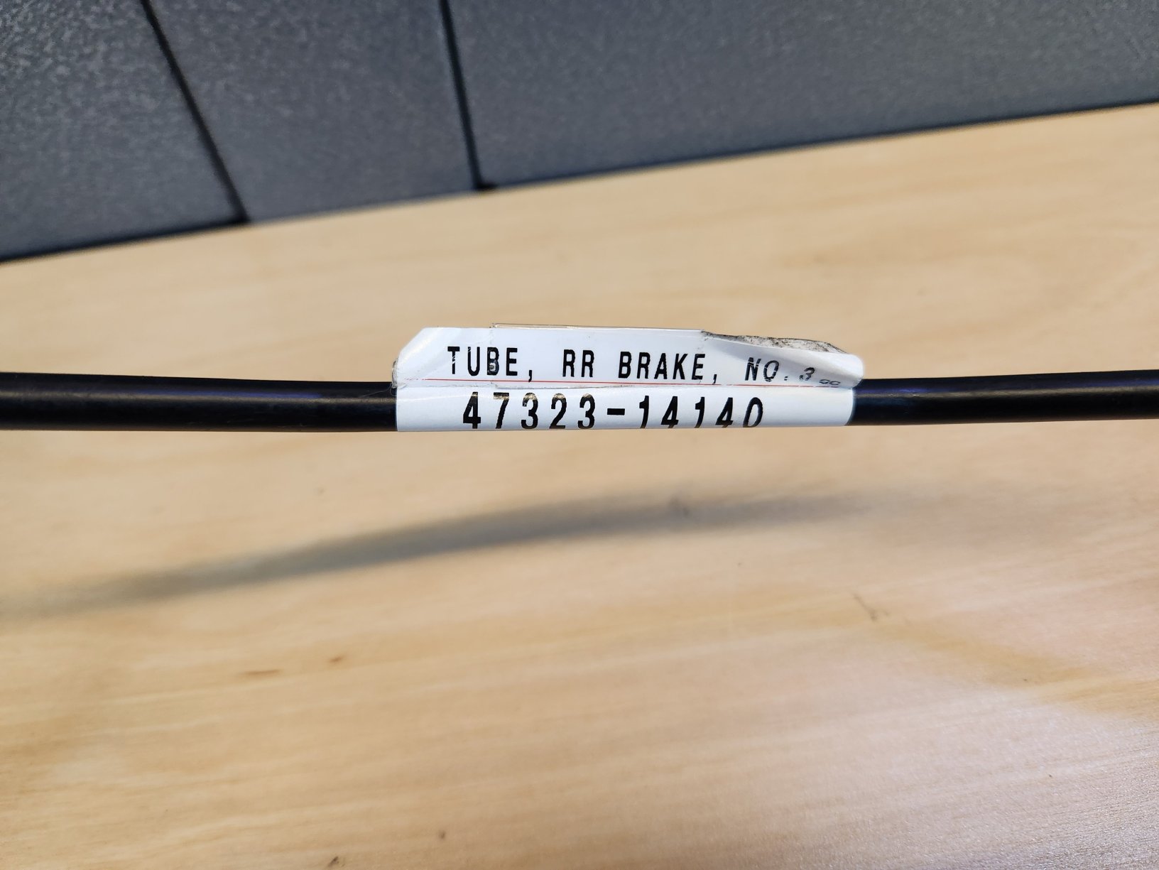
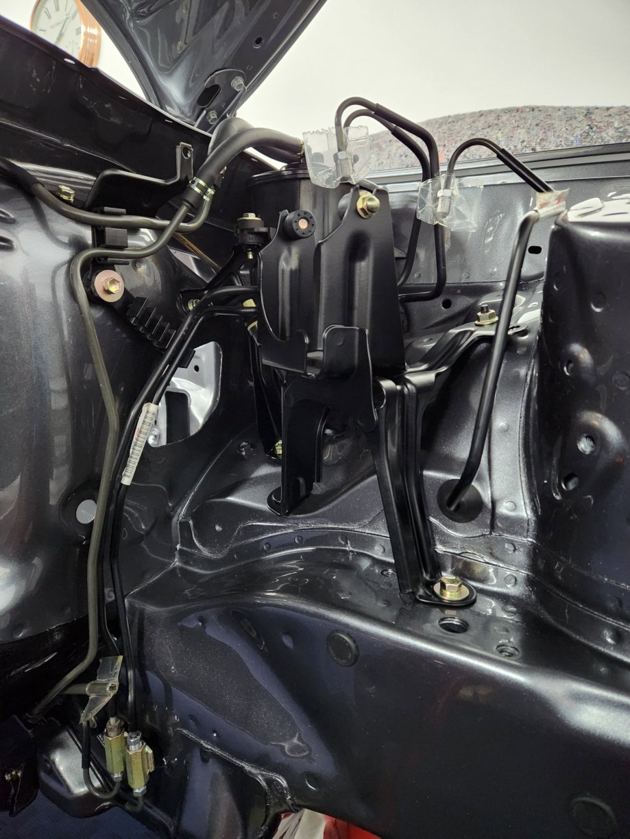
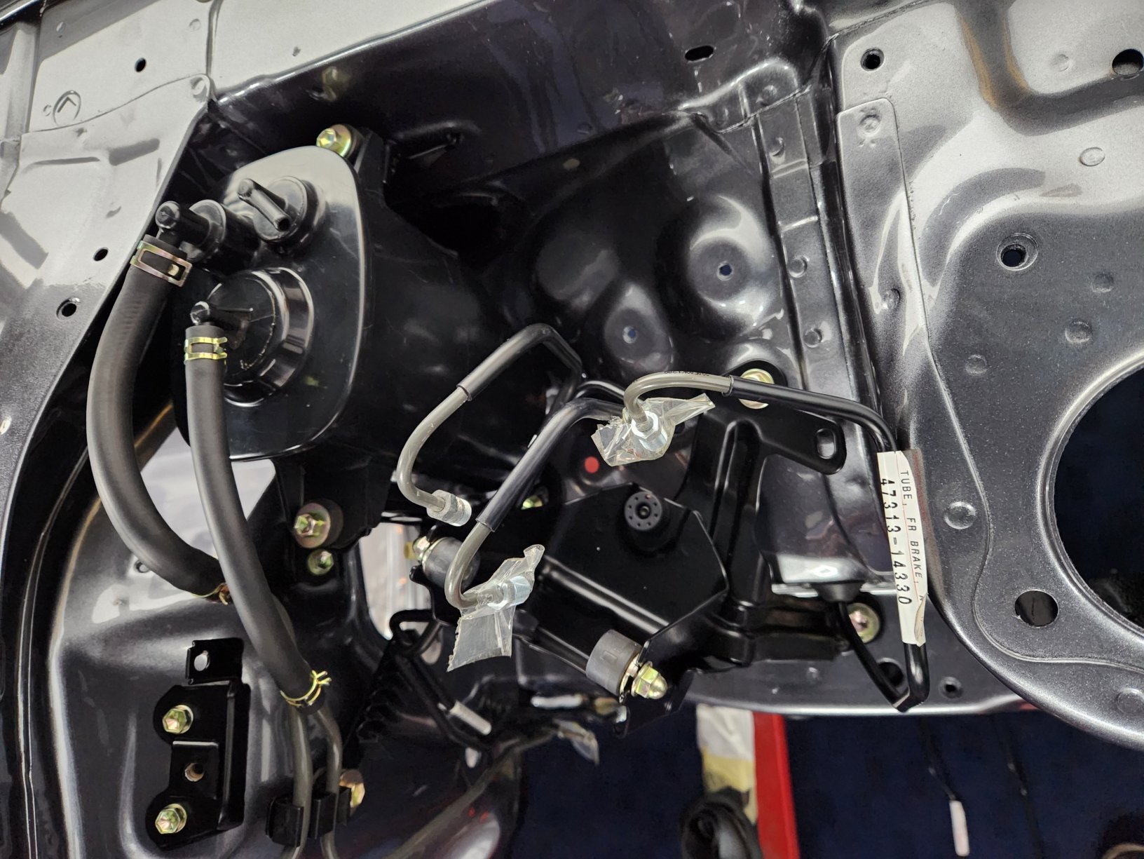
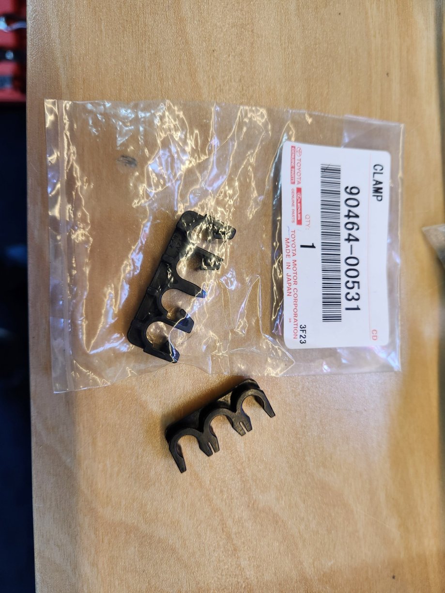
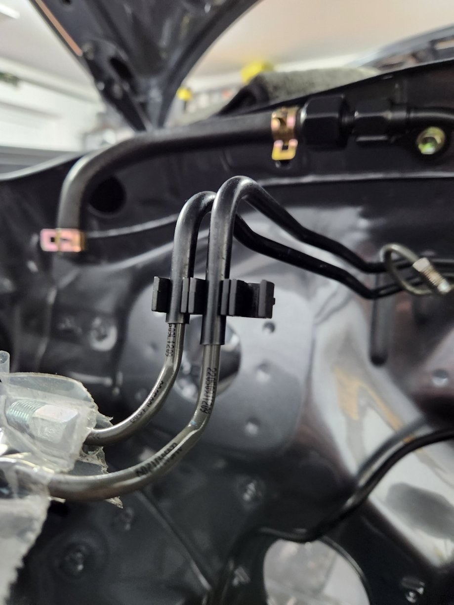
I've now installed the engine bay bulkhead pipe work. First were the two rear brake pipes that rund from the ABS actuator to the union pipe at the base of the nearside of the engine bay. I managed to get pne new a the other I had to reuse as it is now discontinued. I was also able to still get a replacement near side front brake pipe and losely install it. I then installed the two pipes that run from the brake reservoir. These were both new replacements. I then installed the pipe from the clutch reservoir to the gearbox. I reused my original pipe. Finally I installed the offside front brake pipe. This is annoyingly discontinued, so i had to reuse my original pipe. I then installed the two pipe spacers. The larger one goes on the back of thevpipes whwre the HVAC drain pipe comes through the bulkhead. The other spacer separates the two pipes going into the brake reservoir. I then installed the new clutch master cylinder. Although I bought a new guard and bolts I decided to reuse my zinc plated old ones instead. Next was the repainted brake booster.
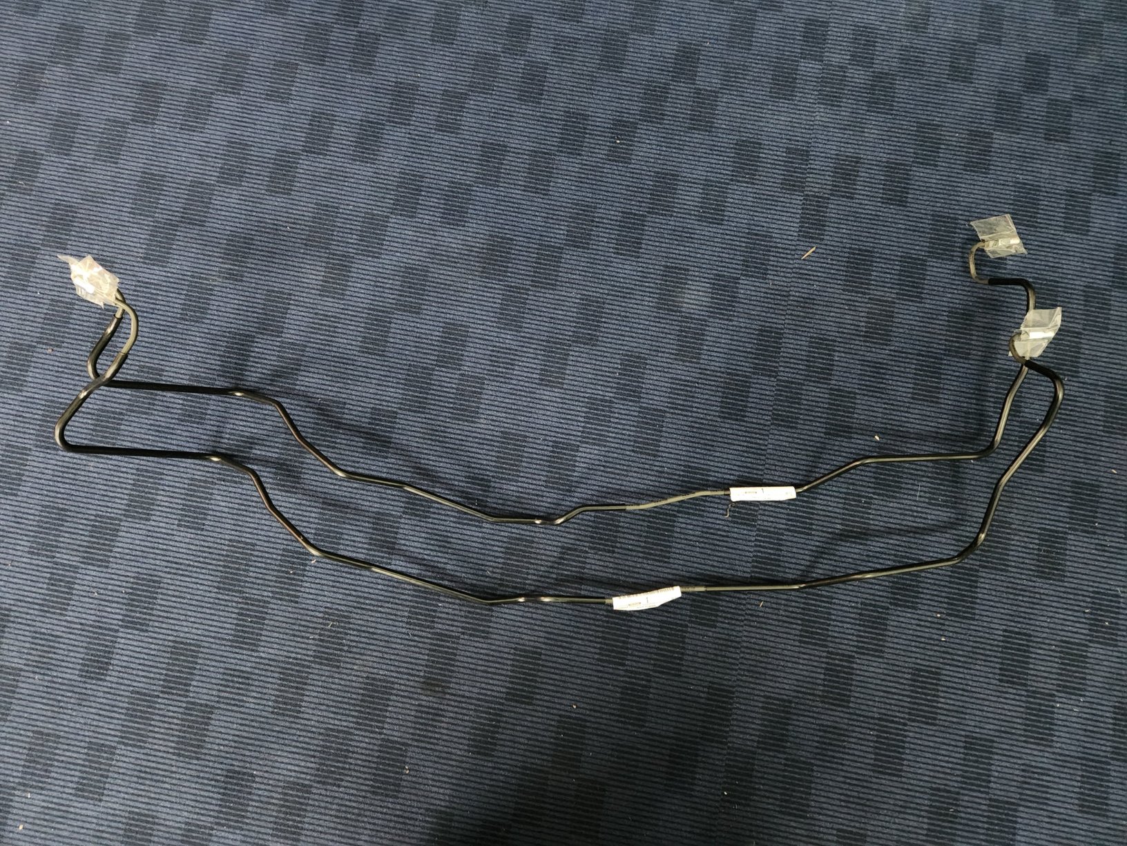
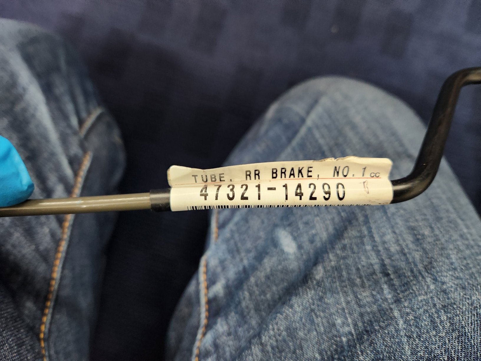
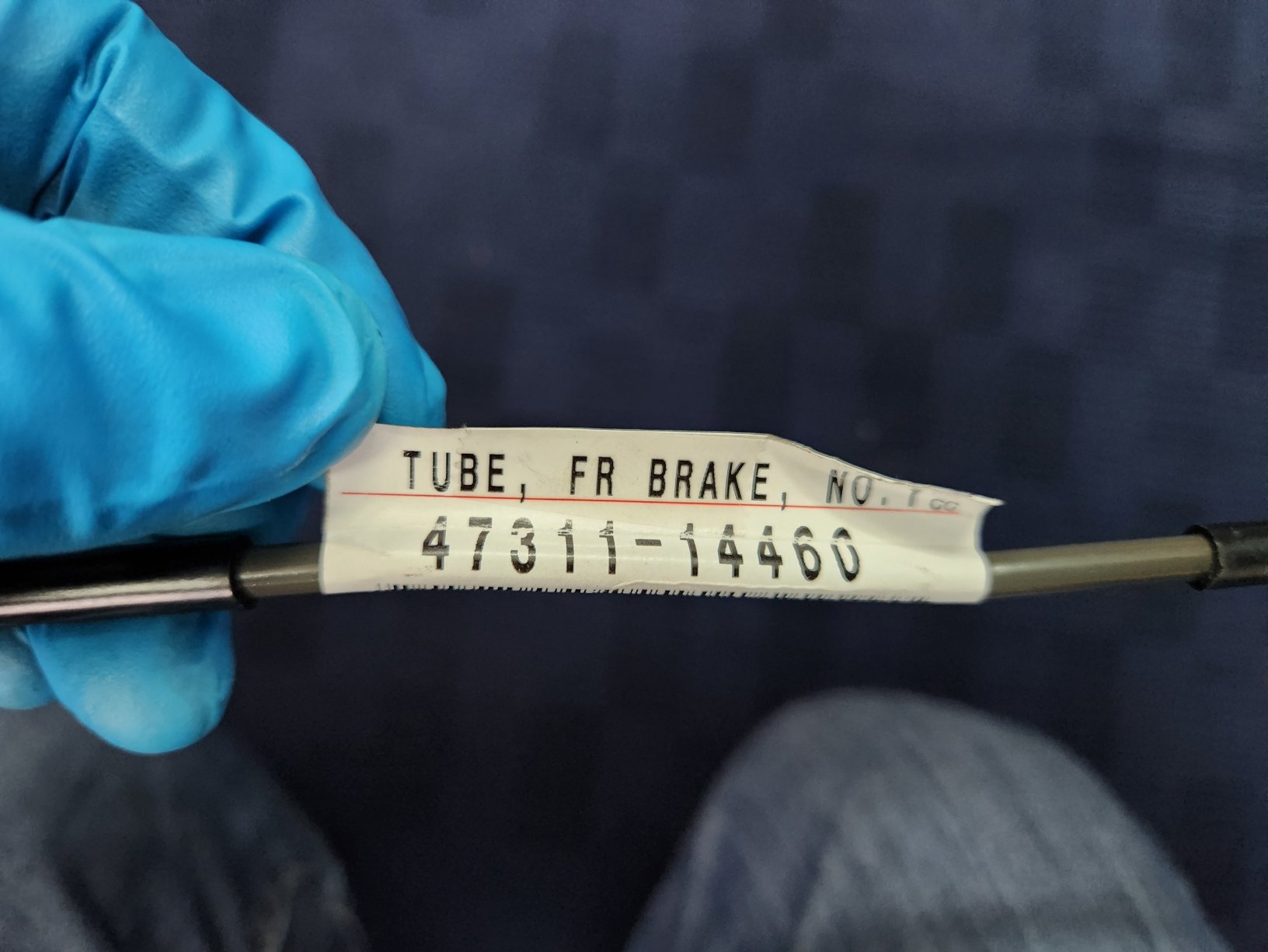
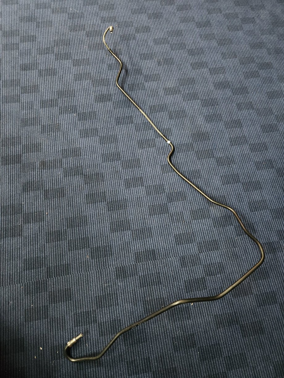
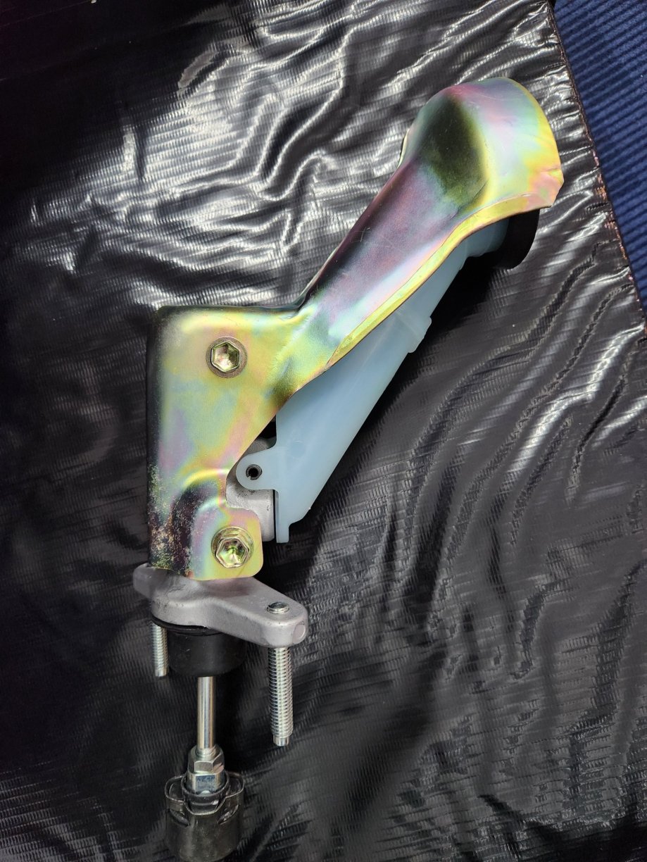
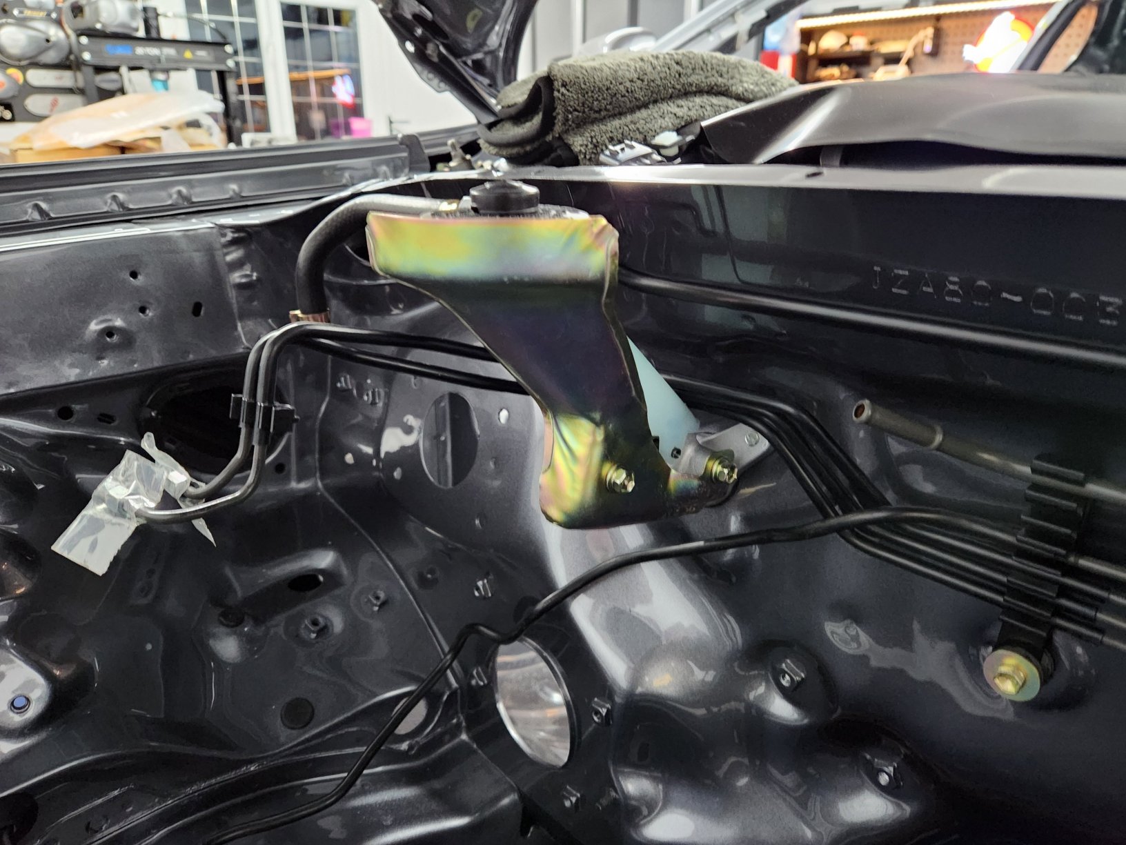
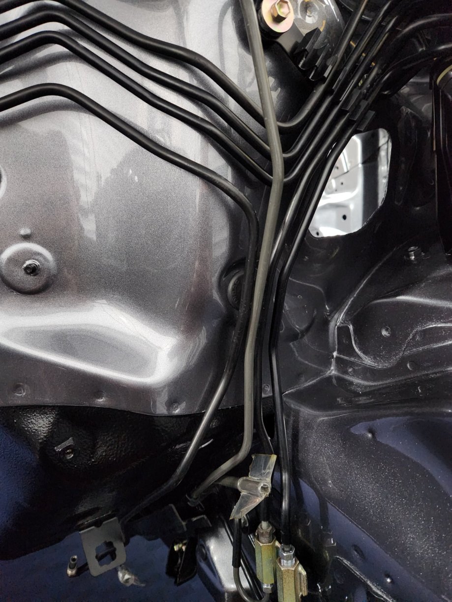
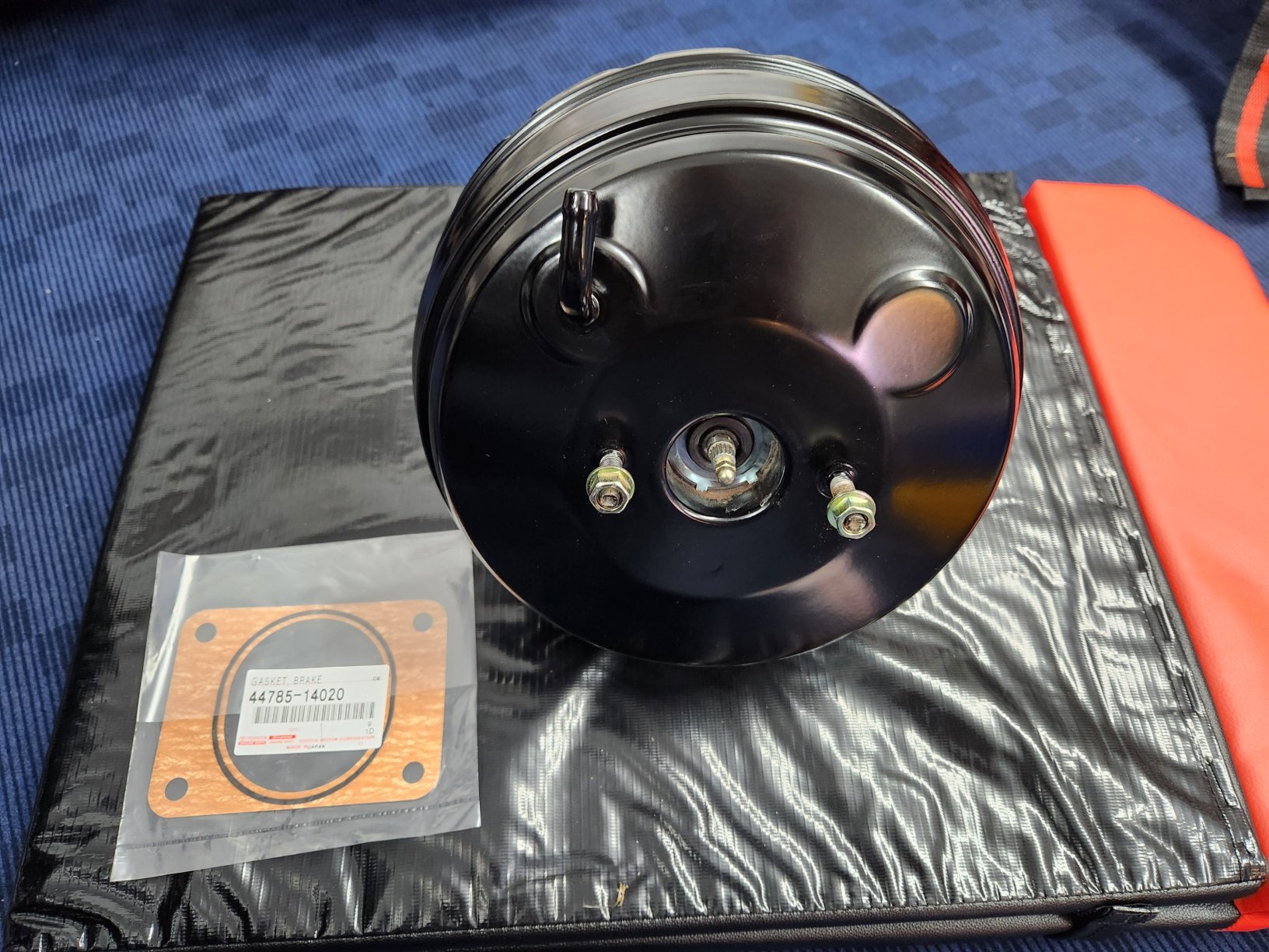
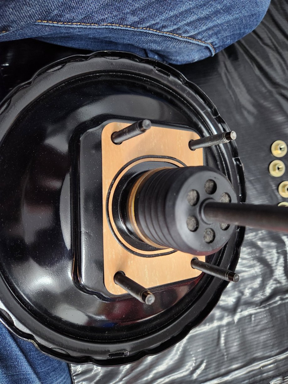
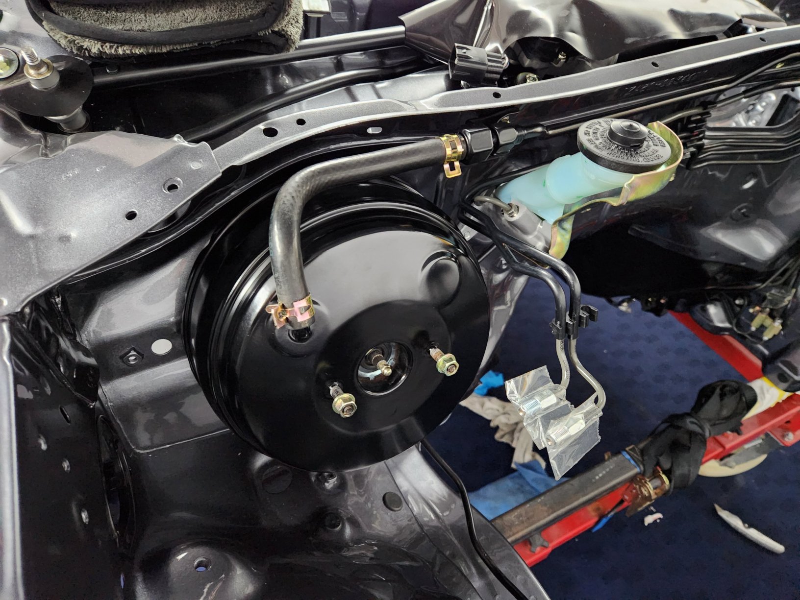
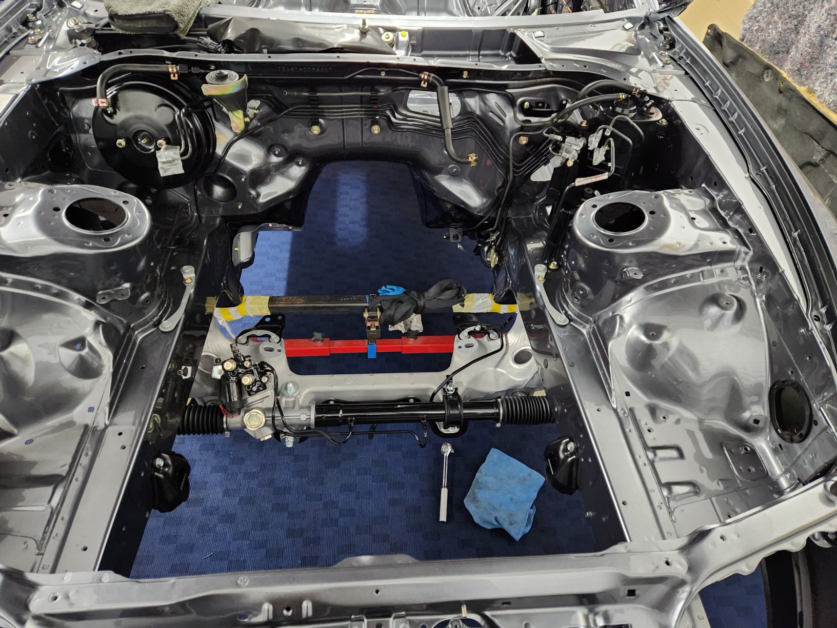 1 point
 -
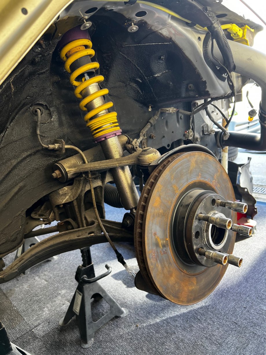
Very retro. It's going to take a bit of getting used to after 27 years on the BBS alloys.
 1 point
 -
Ah! A Donald J Trump thread, I'll have to visit this later Quite appropriate as a customer last week saw a MAGA hat on my bench and asked whose it was. I said it was mine, my wife bought if for me. " Well he said, it doesn't give a very good impression of the sort of person working on my car". I was a bit miffed so had to reply, "If we are judging each other by our personal belongings I wonder what the nodding dog on your parcel shelf says about you?"1 point
-
Hi everyone Im trying to sell my Evo 9 auto wagon. its just sat surpluss to requirements at the moment. She needs some cosmetic work in some areas, and has got a couple of things wrong with her. Buit she is a great car with a fresh MOT. My daily driver for 8 or so years and has been excelent to me. Time to move her on. Happpy to take an offer on price. especialy if its through the forum for a nice easy sale Heres the pistonheads add. Any questions let me know. https://www.pistonheads.com/buy/listing/18145690
.thumb.jpg.62941666eba9b63c4df739e57882abb2.jpg) 1 point
1 point -
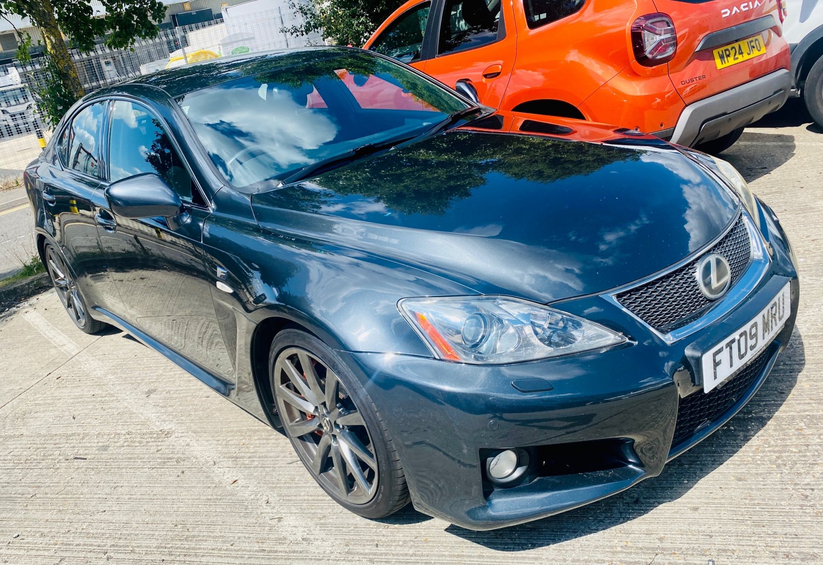
That used to be my car. Bought from Charlesworths around 2003/4 and sold a year later. Beautiful car but running costs and insurance were hefty. Did see it online parked inside an MR2 trader but those images have disappeared off google1 point
-
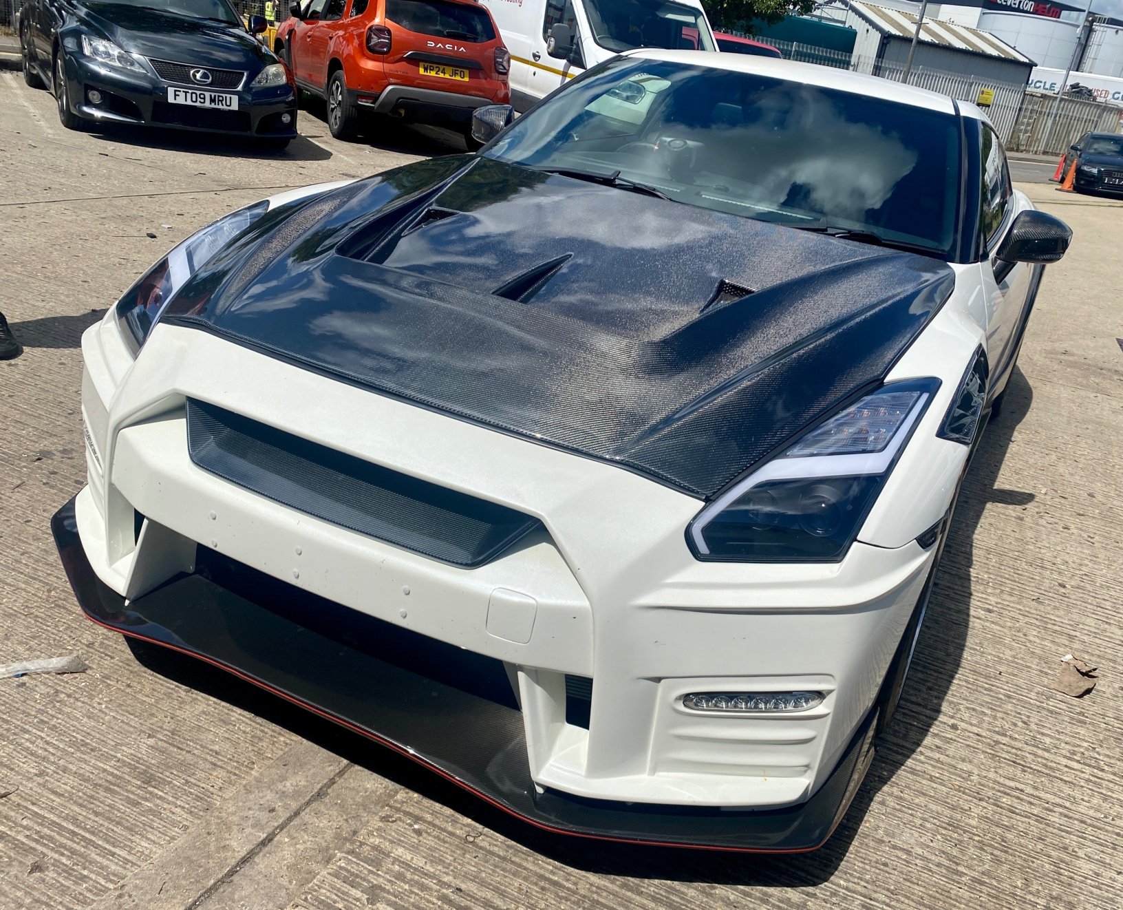
Thought I updated this but obviously not, not long after getting the turbo I also bought an FMIC intake - it’s letting me upload pictures now too
 1 point
 -
~Sunday 22nd September, 12:30pm~ 1. KamaSupra 2. ChrisPank 3. James_cbr 4. DanScoob +1 5. Vinny 6. ZedCharlie 7. 8. 9.
 1 point
 -
~NEXT MEET- 12:30pm, Sunday 22nd September 2024~ ~Sunday 22nd September, 12:30pm~ A little catch up at the meeting point, before a convoy to a local pub for lunch. ~PLEASE NOTE~ The meeting point is no longer in the goods inward area, behind Pets at Home. The meeting point is now at: Unit 4, Templar Court, Knights Park Road, Basingstoke, RG21 6AB Please add your name to the list if you’re attending or ‘maybe’ attending. Thanks~ Dave ~Sunday 22nd September, 12:30pm~ 1. KamaSupra 2. 3. 4. 5. 6. 7.
 1 point
 -
Pics from Augusts meet


 1 point
 -
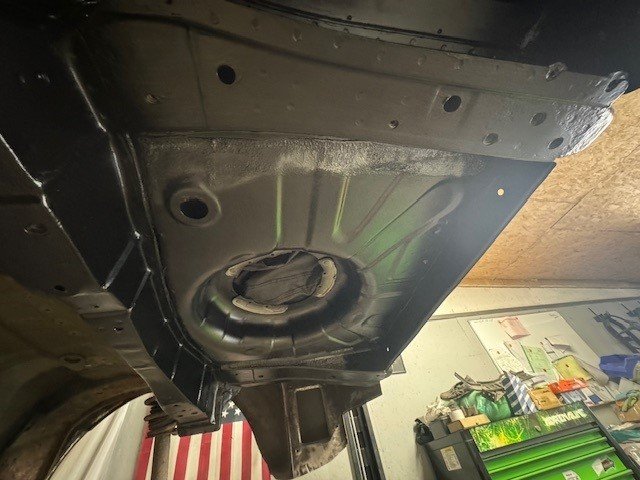
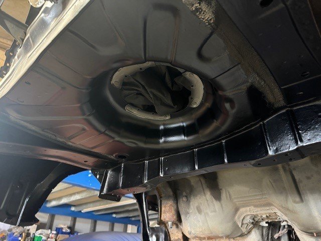
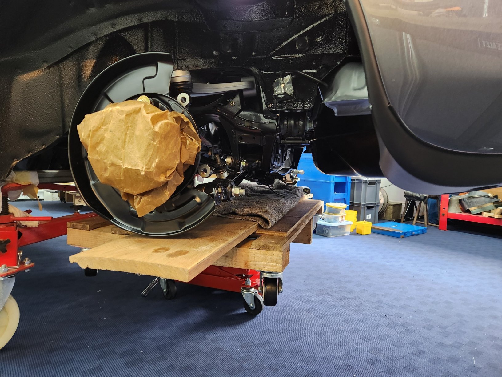
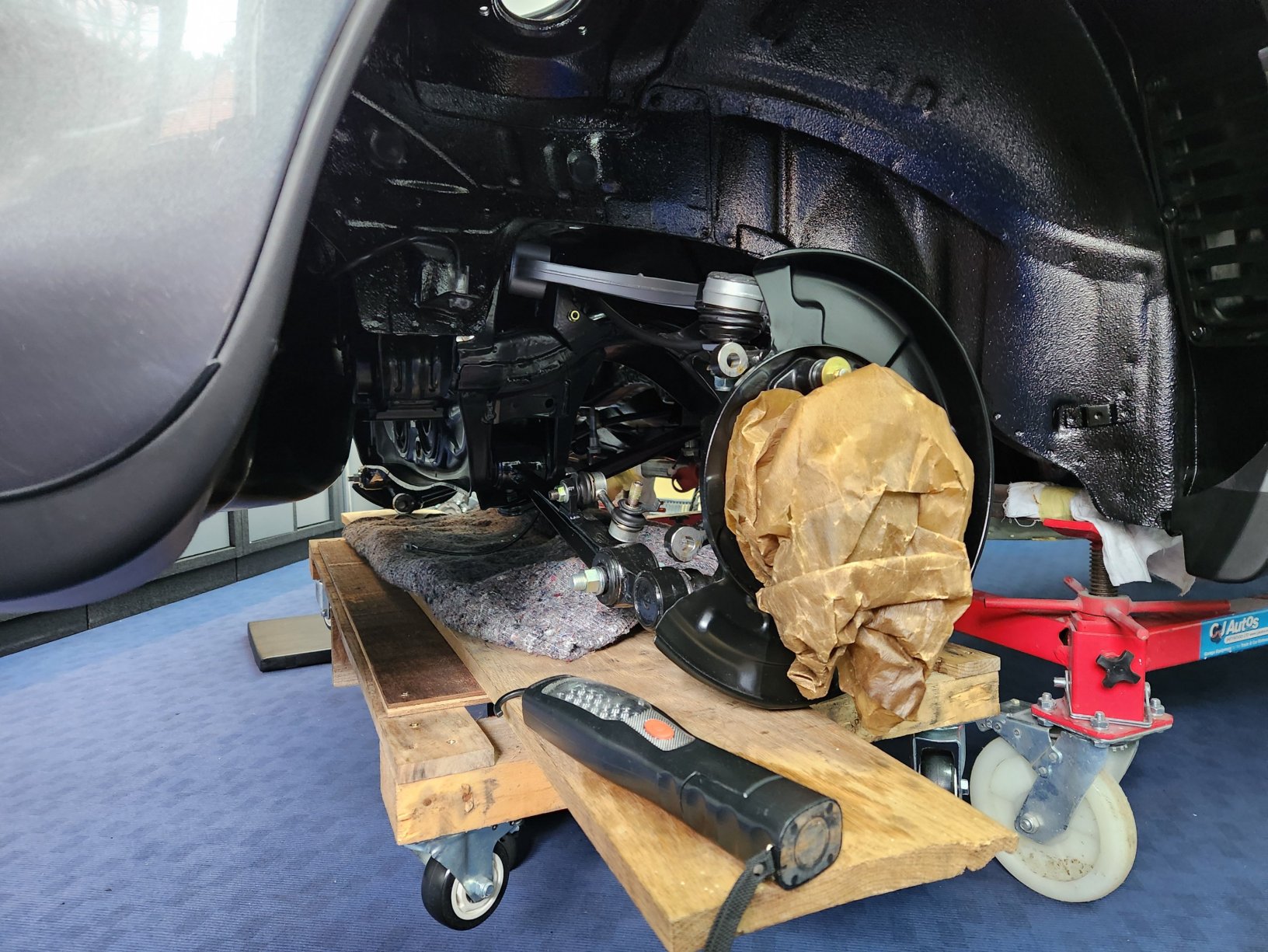
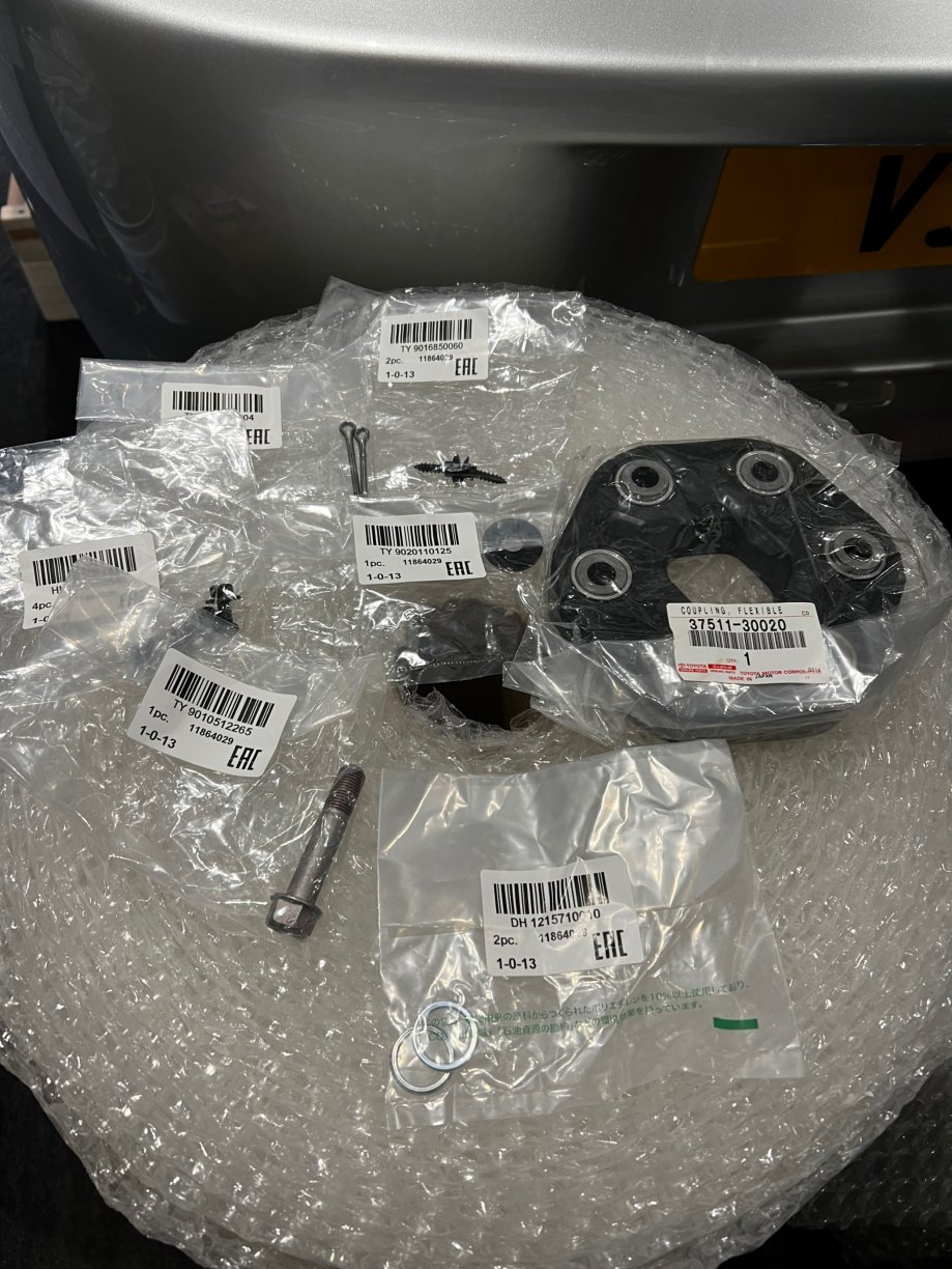
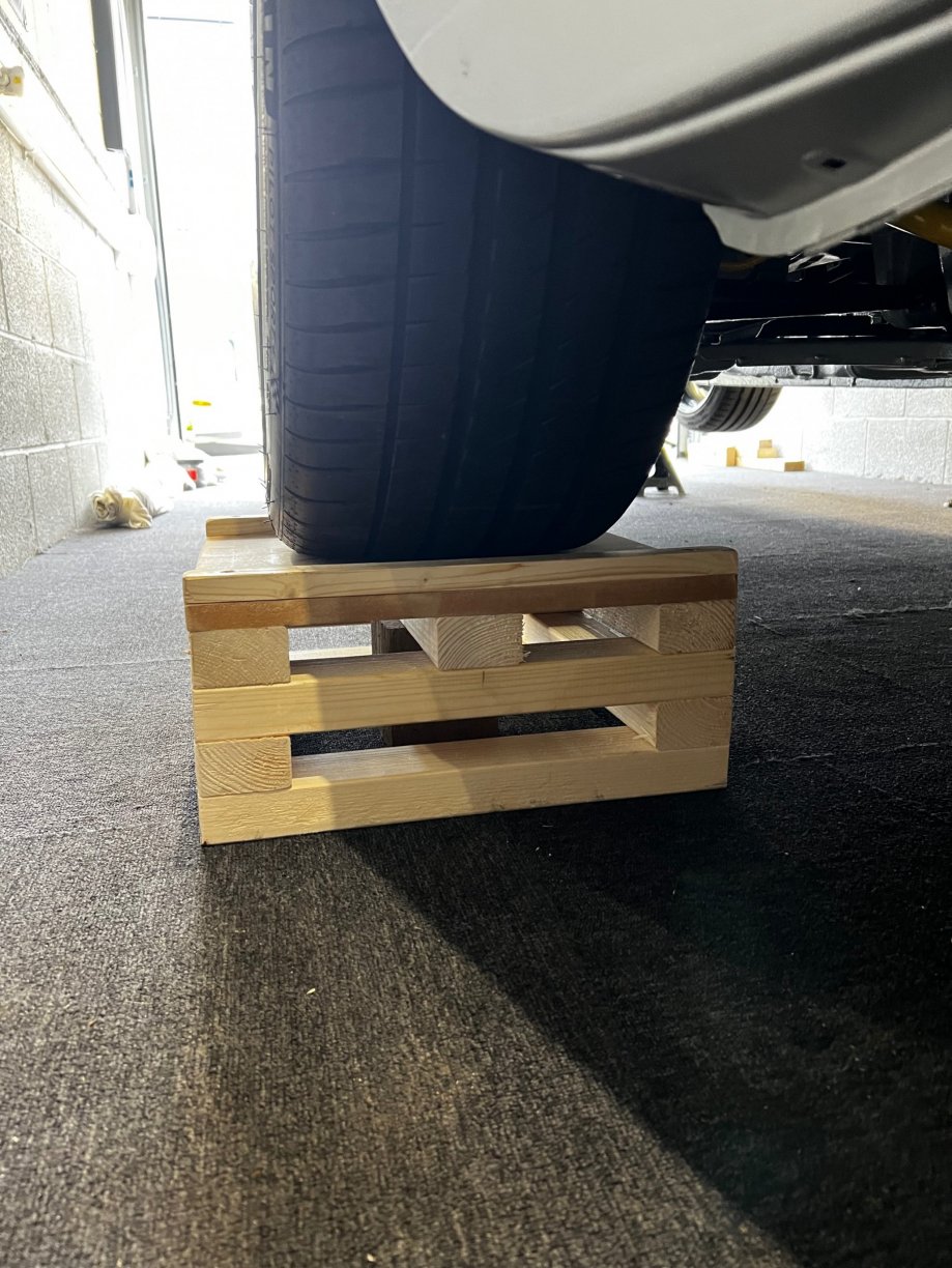
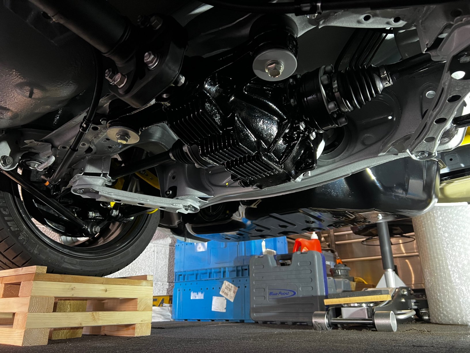
Small package of random bits I missed from Amayama, I noticed when putting the prop back in that the new OEM doughnut was for an N/A so I had to fit the old one for getting the car out. Made some blocks to sit the rear wheels on now the back end is pretty much complete except a few minor things. Removed the prop again to fit the correct doughnut and torqued everything up, got a whiteboard up now so I remember what needs to be torqued and checked. Now it’s on to the front, will sheet the car up and get cracking on taking it all back when I next get the some free hours.
 1 point
 -
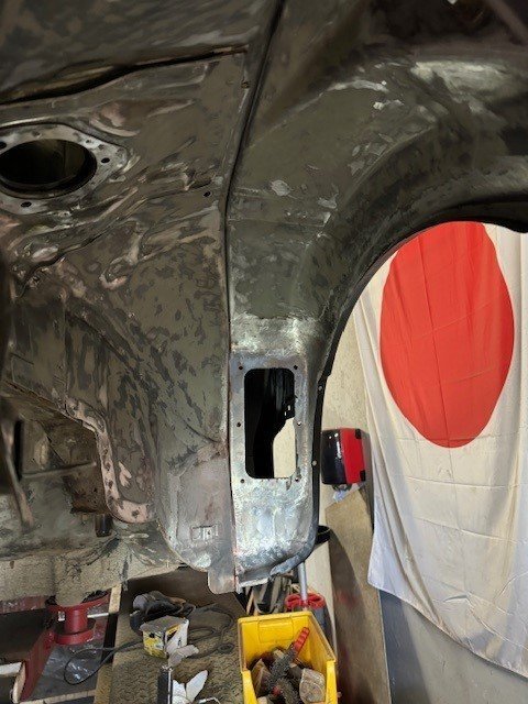
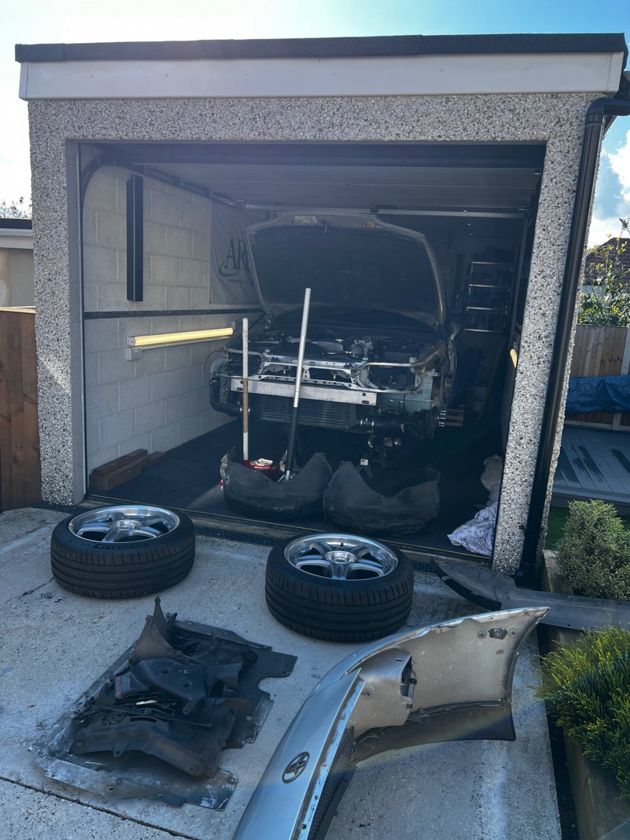
As I had it out the car I decided to take the gear shifter apart to make it look abit better, albeit your never going to see it. Cleaned it up, Hydrate 80 then galv sprayed it to see how the finish would come out. Not perfect but a lot better then it was. Also managed to get the front wings and bumper off this morning to start on the front end. All come off without any snapped bolts to deal with which was nice, little wins are always welcomed!
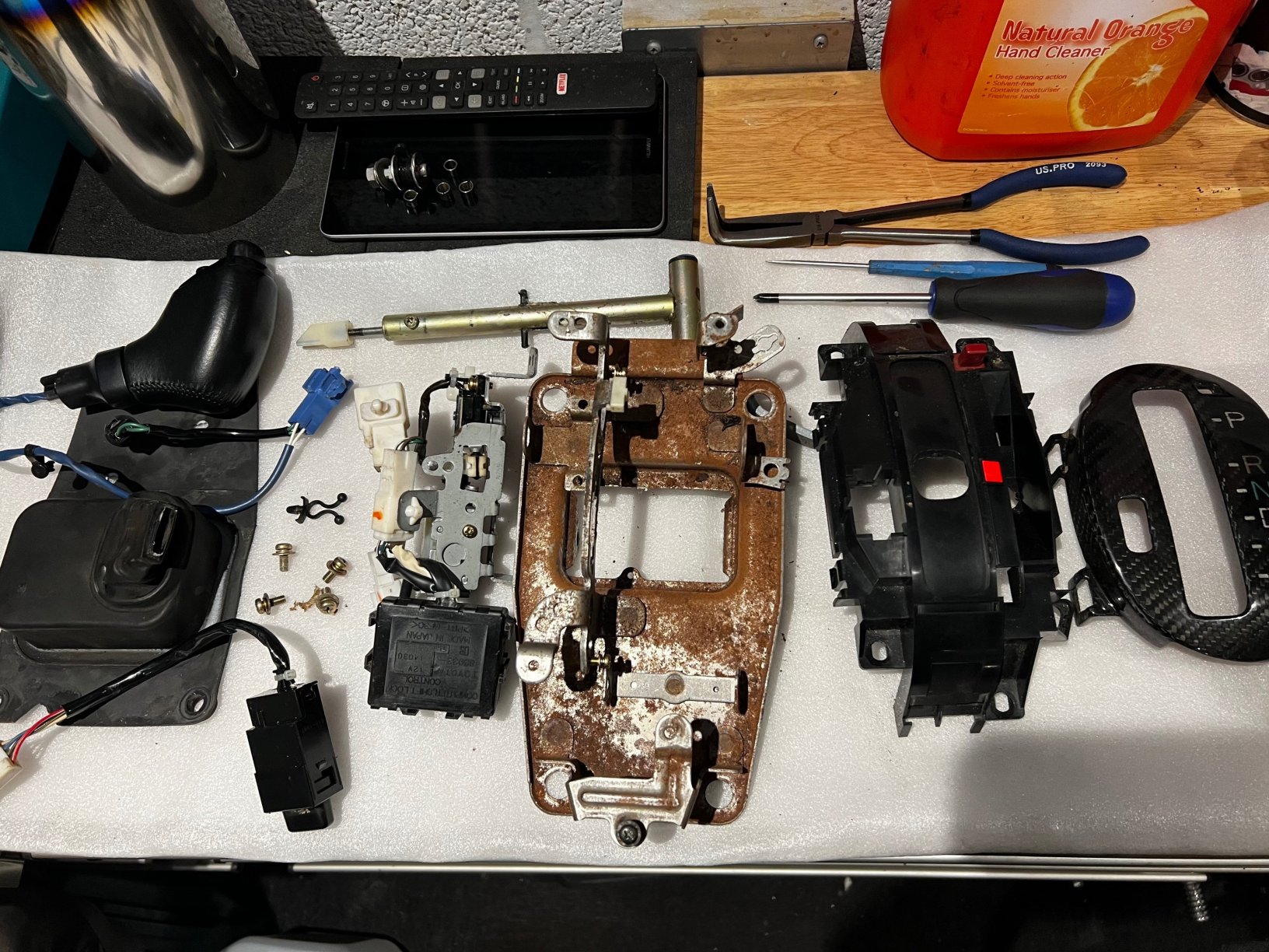
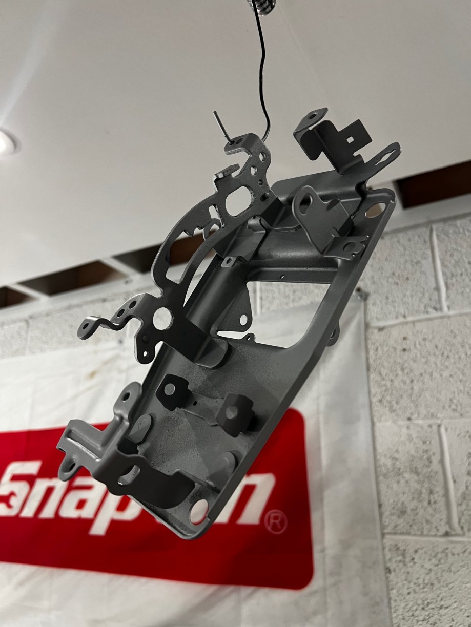
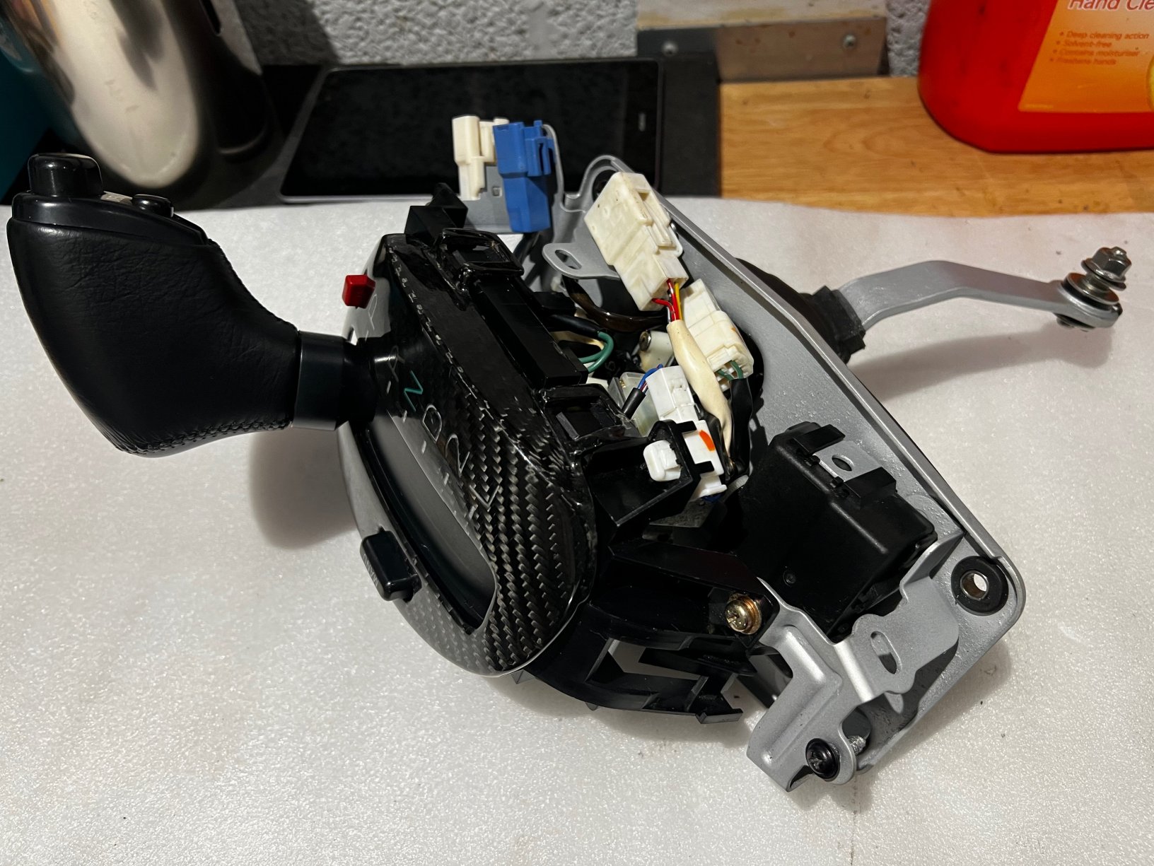
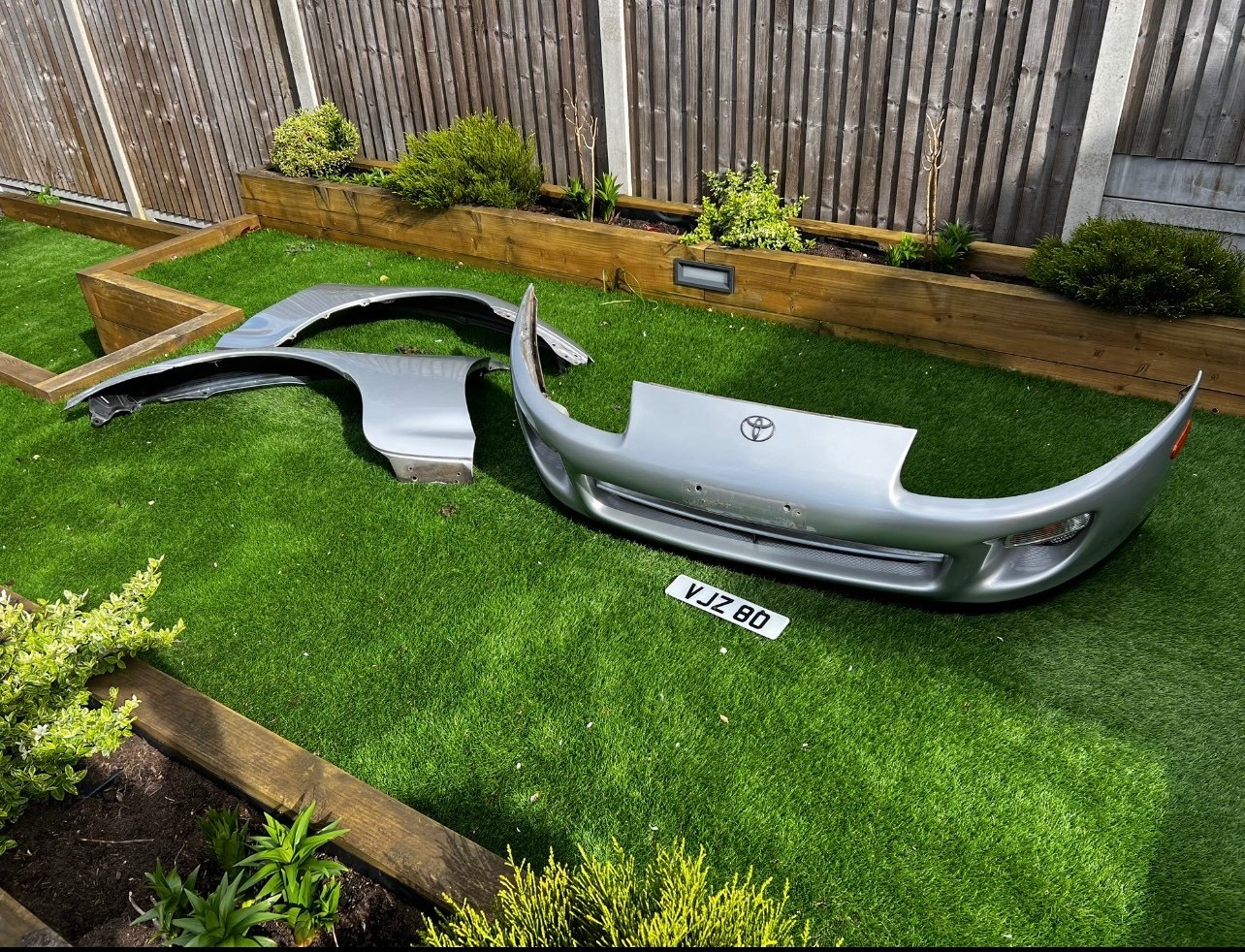 1 point
 -
Ah man, I feel like Ive tried everything. breaking them might be the only way now annoyingly yeh soaked in penetrating oil but not budging even made a tool to push from inside but does nothing0 points


.jpg.346329934667d24adf8148c80e7fdf2c.jpg)


